Die Casting Design Guide: Rules, Tolerances & DFM
A practical die casting design guide: wall thickness, draft angles, fillets, ribs, bosses, tolerances, and DFM rules that reduce tooling cost and improve part quality for aluminum and zinc castings.

Technical Director, Die Casting Engineering
Blog Visual Plan
Article visuals for die casting design guide
These visuals use your current KastMfg image library now, and they will automatically switch to article-specific images when you add them later.
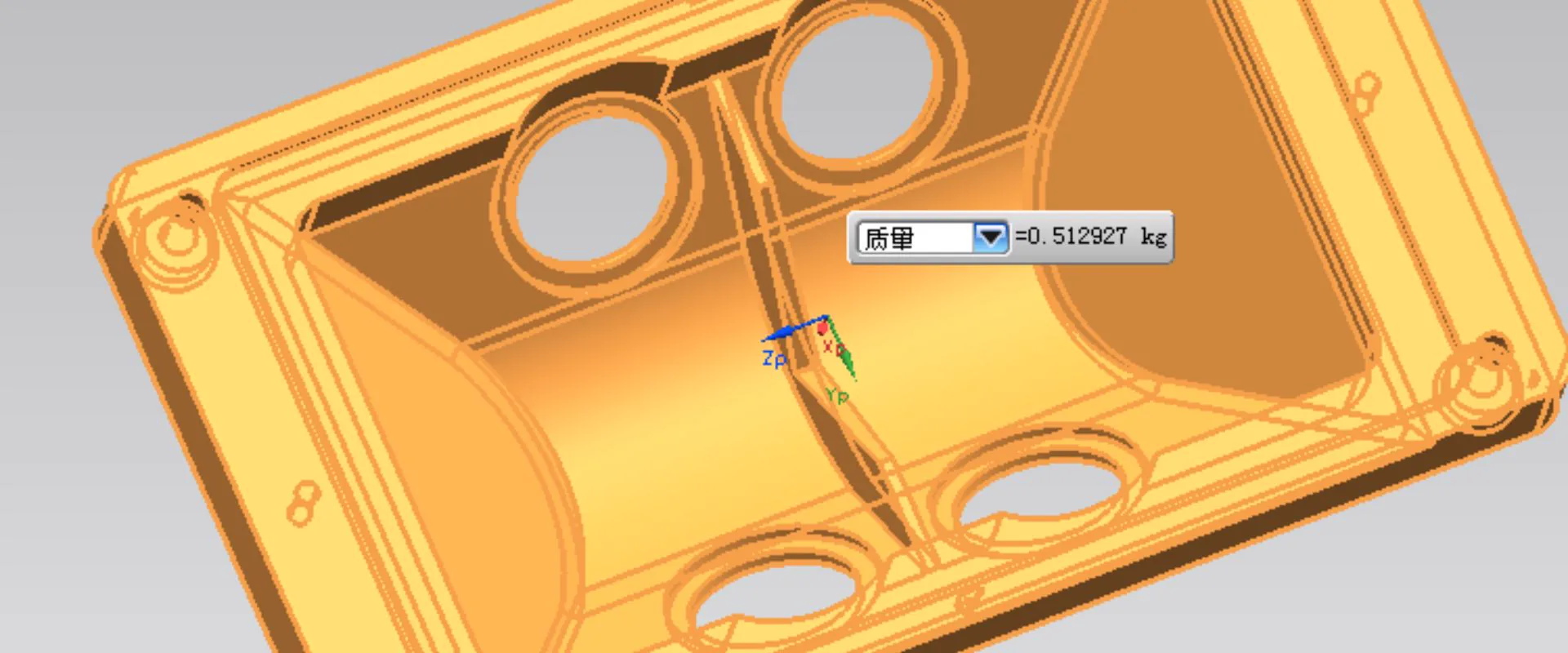
Lead Technical Image
Add a hero-level manufacturing, tooling, or component image that reinforces the article topic above the body copy.
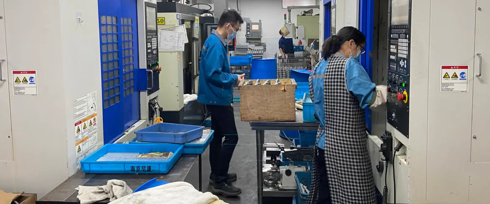
Comparison or Detail Image
Reserve a second image for an alloy comparison, defect example, tooling detail, or application close-up deeper in the article.
Good die casting design is the single biggest lever on part cost and quality - more than the alloy, more than the supplier. A part designed for die casting from the start will quote lower, fill cleaner, hold tolerances better, and run for the life of the tool. A part designed for machining and "adapted" to casting will fight you on every wall, rib, and boss.
This guide collects the DFM rules that matter most, written for buyers and product engineers rather than foundry toolmakers.
The Five Core Design Rules
1. Keep Wall Thickness Uniform
The most important rule. Aluminum and zinc solidify from the outside in; a thick section surrounded by thin walls cools unevenly, creating shrinkage porosity, sink marks, and warpage.
- NADCA guidance: keep sections within about ±10% of the most typical wall to promote even cooling.
- Aluminum: target 1.5-4 mm walls; small, optimized castings can go down to about 0.76 mm, but thin walls increase porosity risk.
- Zinc: target 0.8-2.5 mm; walls as thin as 0.4 mm are feasible thanks to zinc's excellent fluidity.
- Rule of thumb: keep the thickest section below roughly 1.5x the adjacent wall; use cored-out pockets and ribs instead of solid bosses.
A deeper treatment is in the wall thickness guide.
2. Add Draft Angles Everywhere
Draft lets the part eject cleanly from the die. Without it, parts stick, drag, and scratch.
- Aluminum: 1.5-3 degrees on external walls, 2-5 degrees on internal walls and deep features.
- Zinc: 0.5-1.5 degrees - zinc's low shrink and thin walls need less.
- Rule of thumb: more draft on deep ribs and bosses, on textured surfaces, and on internal cores.
See the draft angle guide for exact values.
3. Use Generous Fillets and Radii
Sharp internal corners concentrate stress and disrupt metal flow. A fillet (concave radius) at every wall junction is cheaper than it looks - it improves flow, reduces hot tearing, and extends tool life.
- Internal fillets: NADCA recommends a general radius around 3.5 mm, with roughly 1.5 mm as a practical minimum.
- Rule of thumb: use the largest radius that fits the design.
4. Replace Solid Mass with Ribs
A thick flat section is heavy, slow to cool, and prone to sink marks. Ribs add stiffness without adding mass.
- Rib thickness: 50-70% of the adjacent wall thickness to avoid sink marks on the opposite face.
- Rib height: no more than about 2.5x the rib thickness.
- Rib spacing: keep sections uniform and avoid heavy-to-thin transitions.
5. Design for the Parting Line
Every die has a parting line where the two die halves meet. Where you place features relative to that line determines draft direction, flash location, and secondary machining.
- Keep features that need tight tolerances on a single die half where possible.
- Avoid undercuts - they require slides and add tooling cost.
- Plan where flash will occur and whether it can be trimmed or needs machining.
Tolerances You Can Expect
Standard commercial die casting tolerances follow NADCA and ISO 8062 guidelines. The standard NADCA linear tolerance is ±0.25 mm for the first 25 mm, plus ±0.025 mm for each additional 25 mm:
| Dimension type | Aluminum (typical) | Zinc (typical) |
|---|---|---|
| Linear, first 25 mm | ±0.25 mm | ±0.25 mm |
| Linear, each additional 25 mm | +0.025 mm | +0.025 mm |
| Draft angle | 1.5-3 deg | 0.5-1.5 deg |
Zinc holds slightly tighter practical tolerances than aluminum for the same part because of its lower shrink and thinner walls, but the NADCA baseline is the same. Critical features are almost always finish-machined to tighter tolerances. Full values are in the tolerances guide.
DFM Checklist for Buyers
Before you send a drawing for quote, run this quick self-check:
- Wall thickness uniform? No thick-to-thin transitions over 1.5x.
- Draft on every feature? Internal and external.
- Fillets on internal corners? No sharp re-entrant angles.
- Undercuts minimized? Each slide adds cost and complexity.
- Bosses cored? Solid bosses cause sink marks - core them out.
- Lettering and logos? Raised lettering casts cleanly; recessed lettering needs machining.
A full DFM review is covered in our DFM guide.
How Design Affects Cost
The same part can vary in cost by 2-3x purely through design choices:
- Tooling complexity: slides, lifters, and complex cores each add 10-30% to tooling cost.
- Wall thickness: thinner walls mean faster cycles and less metal - but only to the point fill stays reliable.
- Secondary machining: features designed with draft and tolerance in mind need less machining.
- Surface finish: textured or polished surfaces require more die work and slower cycles.
The cheapest part is the one designed so the casting process does the work, and machining only touches critical features.
FAQ
What is the ideal wall thickness for aluminum die casting?
For most aluminum parts, 2-3 mm is the sweet spot. Walls below 1 mm are possible for small features but increase porosity risk, and walls above 4 mm should be cored out to avoid sink marks and slow cycles.
Do I need to add draft angles myself?
Your supplier's engineers will add draft during DFM review, but designing with draft in mind from the start gives you more control over where material is added and removed. Expect 1.5-3 degrees on aluminum parts.
Can die cast parts have undercuts?
Yes, using slides in the tooling, but every undercut adds tooling cost and complexity. Minimize undercuts where possible, or redesign the part to avoid them.
How do I reduce die casting part cost through design?
Uniform walls, generous draft, cored-out bosses, minimal undercuts, and designing around the parting line are the five highest-impact levers. They reduce both tooling cost and piece price.
Related
KastMfg provides free DFM feedback on every RFQ, applying these rules to your drawing before tooling begins. Send us your part and our engineers will return a design review with a quote within 48 hours.
About The Author
Mike Yao on die casting design guide
Technical Director, Die Casting Engineering
Technical Director at KastMfg with 20+ years in high-pressure die casting, leading engineering and program management across aluminum, zinc, and magnesium programs for automotive, EV, electronics, and medical OEMs worldwide.
View author profileRelated Reading
Keep exploring the blog
Die Casting Wall Thickness - Minimum & Maximum
Die Casting Wall Thickness - Minimum, Maximum and Design Rules by Alloy Die casting wall thickness controls metal flow, cooling rate, porosity risk, part strength, dimensional s...
Mike Yao
7 min read
Thin Wall Die Casting - Design Rules & Limits
Thin Wall Die Casting - How Thin Can You Actually Go? Thin walls are where die casting beats every competing process - and where most design failures happen. This guide gives yo...
Mike Yao
4 min read
Die Casting Draft Angle - Rules & Exceptions
Draft Angle in Die Casting - Rules, Exceptions and How It Affects Tooling Cost Draft angle in die casting is the taper applied to walls, ribs, bosses, holes, and textured surfac...
Mike Yao
8 min read
Aluminum vs Zinc Die Casting - How to Choose
Aluminum vs Zinc Die Casting — Choosing the Right Material for Your Part Aluminum and zinc are the two dominant die casting metals globally, together accounting for over 90% of...
Mike Yao
5 min read