Gas Porosity in Die Casting: Causes and Prevention
Gas porosity die casting guide: formation mechanisms, ASTM E505 classes, X-ray and CT detection, consequences for sealing and strength, and prevention.
Production Capabilities
Defect reference visuals for gas porosity die casting
Defect Identification
Visual references including defect photographs, X-ray inspection, CT scans, and sectioned samples for accurate defect recognition.
Process Control
Tooling adjustments, gating modifications, leak testing, and inspection procedures for die casting defect prevention.
Gas porosity is the most common die casting defect — and the most misunderstood. It is often described simply as "holes in the casting," but the mechanism, distribution, size, and consequences of gas porosity differ fundamentally from shrinkage porosity. Understanding the distinction leads to the correct process intervention.
What Gas Porosity Is
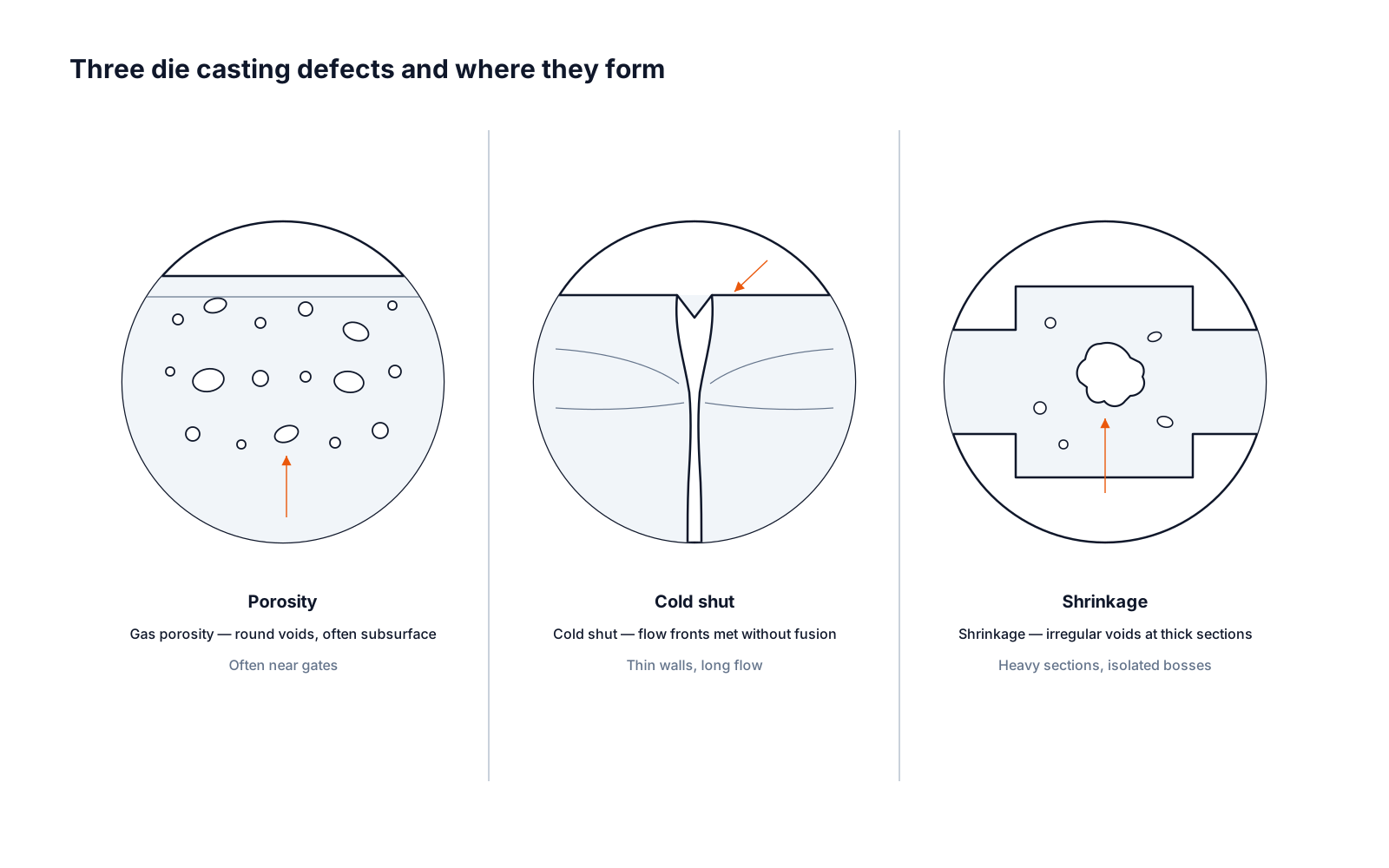
Gas porosity consists of round or nearly round voids distributed throughout the casting cross-section. Under X-ray, they appear as bright round areas against a darker background. Under metallographic cross-section, they show smooth, spherical walls — distinct from the angular, dendritic walls of shrinkage porosity.
These voids contain compressed gas — primarily air entrapped during injection, plus hydrogen released from the aluminum melt.
How Gas Porosity Forms
Air entrapment mechanism: Standard HPDC injects metal at 20-60 m/s at the gate. This turbulent, high-velocity flow folds the cavity air into the metal stream as bubbles. The bubbles cannot escape before the metal solidifies — they are frozen into the casting as distributed gas porosity.
Hydrogen mechanism: Aluminum melt absorbs hydrogen from atmospheric moisture, from wet or contaminated ingot, and from die lubricant decomposition. As the metal solidifies, hydrogen solubility drops sharply — hydrogen gas precipitates out of solution, forming small distributed pores throughout the casting.
Gas Porosity vs Shrinkage Porosity
| Characteristic | Gas Porosity | Shrinkage Porosity |
|---|---|---|
| Shape | Round, smooth walls | Angular, branching, dendritic |
| Location | Distributed throughout section | Concentrated in thick sections |
| Cause | Entrapped gas | Solidification shrinkage |
| X-ray appearance | Round bright spots | Irregular branching patterns |
| Prevention | VADC, gate optimization | Uniform wall thickness, intensification |
ASTM E505 Classification
ASTM E505 defines reference radiographs for aluminum die casting porosity classification (Class 1 = least porosity, Class 5 = most):
| Class | Porosity Level | Typical Application Acceptance |
|---|---|---|
| Class 1 | Near-zero | Pressure-tight hydraulic, T6 structural |
| Class 2 | Very low | EV structural, safety-critical |
| Class 3 | Low-moderate | General structural, pneumatic |
| Class 4 | Moderate | Non-structural enclosures |
| Class 5 | High | Cosmetic / decorative parts only |
Consequences of Gas Porosity
For pressure-tight applications: Interconnected pore networks form leak paths through casting walls. At 100 bar, a pore network connecting an internal passage to the exterior surface is a functional failure.
For T6 heat treatment: During solution treatment at 480-540°C, gas in pores expands. If the surface is thin, this expansion creates visible blisters — destroying the part. Standard HPDC A380 cannot be T6 treated reliably because of this.
For fatigue life: Pores act as stress concentrators. Fatigue cracks initiate at pore surfaces under cyclic loading, reducing fatigue life compared to a pore-free casting.
Detection Methods
X-ray (digital radiography): Standard production screening. Detects pores >=0.3 mm diameter. Classification per ASTM E505. Fast enough for 100% production inspection on qualifying programs.
CT scanning: Volumetric mapping of porosity distribution. Used for tooling qualification and root cause investigation. Not practical for 100% production inspection.
Metallographic cross-section: Destructive. Provides definitive characterization of pore morphology, size, and distribution. Used for process development and failure analysis.
Pressure/helium leak test: Detects interconnected porosity (leak paths). Does not detect isolated closed pores. The most functionally relevant test for pressure-tight applications.
Prevention Strategies
Vacuum-assisted HPDC (VADC): Evacuates die cavity to <30 mbar before injection. Metal enters a near-vacuum — no air to compress and entrap. Reduces gas porosity 60-90%. The primary approach for Class 1-2 requirements and T6 programs.
Gate velocity optimization: Slower gate velocities produce less turbulence and less air entrainment. Trade-off: slower fill increases cold shut risk in thin sections. KastMfg optimizes gate velocity per program to balance fill quality and porosity.
Overflow wells: Capture cold metal and entrained air from the flow front before it reaches the main casting section. Relocates the worst porosity from the casting to the overflow, which is removed.
Degassing: Rotary degassing with argon or nitrogen removes dissolved hydrogen from the melt before casting. Standard practice on all KastMfg aluminum programs.
Alloy selection: A413's near-eutectic composition produces inherently lower shrinkage porosity than A380 — combined benefit when both gas and shrinkage porosity must be minimized.
Porosity consultation: casting@kastdiecast.com | +86 138 1403 4409
Frequently Asked Questions
How do I tell gas porosity from shrinkage porosity on a received part?
Location and shape are the fast tells. Gas porosity shows as rounded, smooth-walled holes, often small and scattered, frequently just under the surface or in last-to-fill regions; shrinkage shows as angular, ragged, branched voids concentrated in thermal centers — thick sections, junctions, bosses. On a fracture or machined face, gas holes look like smooth round pits, shrinkage like torn sponge. When the void sits in a heavy section at a wall junction, suspect shrinkage first; when identical small round pores appear across thin sections or on the as-cast surface, suspect gas. Sectioning or X-ray confirms the call before you reject a lot.
When should I reject a casting for porosity?
Reject against the acceptance criteria on the drawing, not against appearance. If the drawing specifies an X-ray grade per zone (E505-style references for aluminum die castings), a part is acceptable when it meets the grade in each zone — a visible pore in a non-critical zone may be perfectly compliant. Reject when porosity sits in a designated critical zone above grade, crosses a sealing or bearing surface, or causes a leak in a pressure-tightness test. If the drawing is silent on porosity, the practical escalation is: quarantine the lot, section or X-ray samples, and agree a written criterion with the supplier before shipping — subjective rejections are how disputes start.
Why do castings have porosity but machined bar stock does not?
Molten metal absorbs and traps gas, and shrinks as it solidifies — a casting solidifies from liquid in a mold, so both processes leave voids unless actively managed. Bar and billet are typically rolled or forged from an ingot that was itself carefully cast, then worked and inspected; the working closes and redistributes what little porosity exists, which is why machined-from-billet parts are dense at the cost of machining away much of the stock. Die casting manages porosity with injection control, venting, vacuum assistance, and gate design rather than eliminating it — "porosity-free die casting" is not a realistic specification; zoned acceptance criteria are.
The foundry says the porosity is "the nature of the part" and cannot improve. True?
Sometimes it is, and sometimes it is a conversation-ender. The claim is legitimate when the geometry genuinely sets the limit — a thick-heavy section isolated from feeding, a gate and vent scheme the die cannot support, a tolerance scheme that machines into trapped gas. It is not legitimate as a first response before anyone has looked at the process data. The professional counter is to ask for evidence in the caster's own language: section-by-section porosity ratings against ASTM E505 reference radiographs, porosity distribution from CT or sectioned parts, and what changed when venting, gating, or shot profile was last adjusted. A caster who shows that data and explains which limits are geometric is being straight with you; one who reaches for "nature of the part" before the data exists is telling you what they would rather not change.
My dyed anodize bleeds out of a cast aluminum part after sealing — is the anodizer at fault?
Usually not, and the anodizing thread that settles it is blunt: sealing does nothing to the porosity inherent in the casting. Dye bleeds from dye entrapped in casting pores — voids that sit under or connect through the anodic film. The anodic layer grows from the aluminum around each pore; where a pore intersects the surface, the film is perforated or bridged thin, dye wicks into the void during coloring, and no sealing rinse pulls it back out. The result shows up days later as dark bleed spots or white bloom around pores, and it tracks casting porosity, not anodizing skill.
The three remedies, in rising cost order:
- Impregnation before anodizing. Resin-impregnating the casting seals subsurface voids first, so dye has nowhere to wick into. The standard route for cast parts that must carry dyed anodize.
- HIP (hot isostatic pressing). Closes internal porosity outright by heat and gas pressure — effective but a separate process step with its own cost and logistics; justified when mechanical fatigue performance is also in play.
- Nitric-acid / desmut process discipline. Long, warm dye baths and aggressive pre-treatments give entrapped chemistry more time to work back out; shorter cycles, lower dye temperatures, and prompt sealing reduce bleed without fixing the underlying porosity. This is mitigation, not cure.
The structural fix is upstream: porosity-conscious process control in the casting — vacuum assist, shot profile, gating — reduces the pore population the finish has to live with. If the drawing requires dyed anodize on a high-pressure die casting, say so at DFM review; the alloy, process, and impregnation decisions all change with the finish in view, and high-silicon alloys carry their own anodizing limits independent of porosity.
Related Defect & Quality Guides
Related Resources
Next steps for gas porosity die casting
Shrinkage Porosity Die Casting: Causes and Fixes
Shrinkage porosity die casting guide: why it forms in thick sections, how to distinguish it from gas porosity on X-ray, and design and tooling prevention.
Defect GuideDie Casting Soldering Defect and Blistering Guide
Die casting soldering defect and blistering guide: why aluminum bonds to die steel, how blisters form during T6 heat treatment, and prevention methods.
Quality GuideDie Casting Defects
Compare common defect types, causes, and corrective actions from a buyer and engineering perspective.
CapabilityQuality Control
Review inspection workflow, traceability support, and process control standards before launch.
Process GuideDie Casting Process
See how casting, trimming, machining, finishing, and inspection fit together in production.
Next StepRequest a Quote
Send your drawing package and target volume to get an engineering-backed quotation.
Need a Quote for Your Project?
Our engineering team is ready to review your requirements and provide competitive pricing with fast turnaround.
Request a Quote