Plating for Die Casting | Zinc & Aluminum Finishes
plating and finishing for die casting parts, including zinc die cast hardware, cosmetic parts, corrosion protection, and assembly-ready components.
Production Capabilities
Supporting visuals for zinc die casting plating
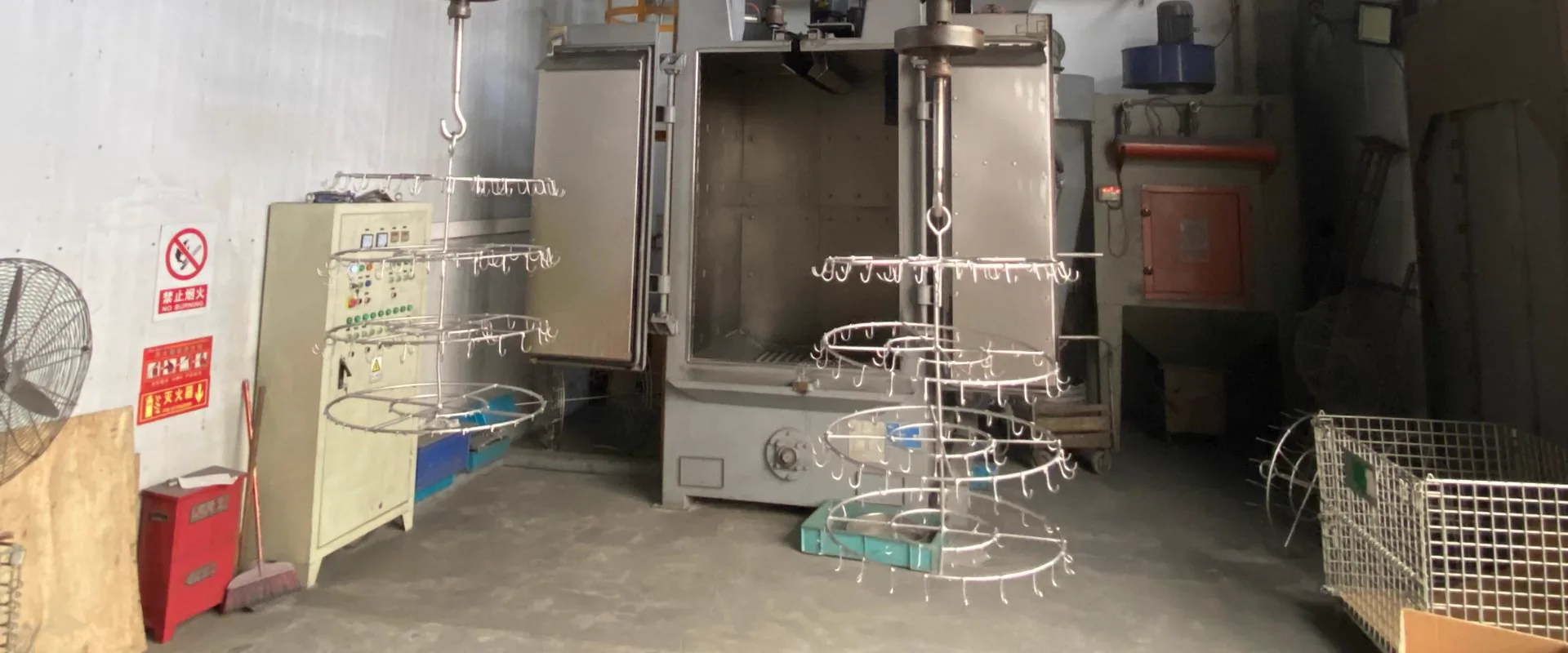
Production Workflow
Die casting machining, finishing, tooling, and assembly operations at our Nanjing facility.
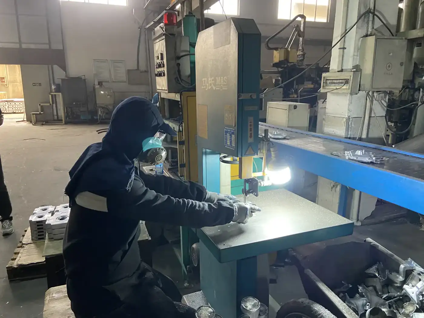
Quality Detail
Close-up views of tooling precision, machined features, surface finishes, and inspection procedures.
Plating is a standard requirement for zinc die cast hardware, lock components, connector housings, decorative parts, and corrosion-resistant assemblies. For an OEM engineer specifying the surface finish, the two decisions that matter are which plating system the part needs and what must be written on the drawing so the coating is applied consistently at production volume. This page covers both, for zinc and aluminum die cast substrates.
KastMfg casts the parts, then coordinates plating and related surface finishing through qualified finishing partners, managed under our die casting and inspection workflow. The plating specification, cosmetic standard, and test requirements are agreed with you before tooling release and verified at first article.
For the full finishing menu including powder coating, anodizing, and e-coating, see die casting surface finishing.
Why Zinc Die Castings Plate Better Than Aluminum
The substrate decides how well decorative plating works. Zinc die castings in Zamak 3 and Zamak 5 are the global default substrate for decorative chrome and nickel plating for three reasons:
- Dense, smooth as-cast surface. High-pressure hot-chamber casting produces a fine-grained, low-porosity surface skin. Zamak casts at Ra 0.8-1.6 μm as-cast — smoother than any aluminum die casting alloy — so the plating needs little mechanical leveling to reach a mirror finish.
- Stable alloy chemistry. Zamak's tight impurity limits (Pb, Cd, Sn) prevent inter-granular attack during the acid pretreatment steps, so adhesion failures are rare on material from certified SHG zinc.
- Established process route. Copper strike / nickel / chrome on Zamak is a mature, widely qualified process with published thickness and test benchmarks your finishing partner can quote against.
Aluminum die castings follow a different route. The common die casting alloys (A380, ADC12) contain roughly 8-12% silicon, which makes anodizing patchy and uneven, and aluminum's tenacious oxide prevents direct electroplating adhesion. Electroplating aluminum requires a zincate pretreatment — typically a double zincate cycle — followed by a copper strike before the nickel and chrome layers, and casting porosity can trap process solutions and cause blisters or pits. Decorative chrome on aluminum die castings is therefore the exception, not the rule.
The practical consequence for part design: if the part needs a bright decorative metallic finish, specify a zinc alloy. If the part must be aluminum — for weight or thermal reasons — plan on anodizing (Type II or III where the alloy allows), powder coating, or chromate conversion coating instead of decorative electroplate. The surface finish comparison guide maps finish options to alloys in detail.
Standard Plating Systems for Zinc Die Castings
The workhorse decorative system on Zamak is copper–nickel–chrome. Typical layer thicknesses:
| Layer | Typical Thickness | Function |
|---|---|---|
| Copper strike | ~5 μm | Adhesion bridge between zinc and nickel; seals the surface |
| Acid copper (optional) | 10-15 μm | Levels polishing marks and minor casting texture |
| Semi-bright nickel | 8-15 μm | Ductile corrosion barrier; takes most of the load in corrosion tests |
| Bright nickel | 5-10 μm | Mirror gloss and color |
| Decorative chrome | 0.2-0.5 μm | Hard, tarnish-resistant top layer; blue-white color |
Total thickness for a production decorative system is typically 20-30 μm. Functional coatings are thinner: zinc plating and plain nickel coatings on castings typically run 5-20 μm, and decorative chrome alone — sometimes specified over an already-plated or polished substrate — contributes under 1 μm.
| Finish | Typical Thickness | Best Fit |
|---|---|---|
| Decorative chrome over nickel | 20-30 μm total system | Bathroom fittings, automotive trim, lock hardware, consumer products |
| Bright or satin nickel | 10-20 μm | Hardware, connectors, fashion and decorative parts |
| Zinc plating (functional) | 5-20 μm | Sacrificial corrosion protection on functional zinc and steel parts |
| Gold, copper, antique finishes | Varies | Specialty decorative hardware |
Common plating applications we support:
| Application | Typical Requirement |
|---|---|
| Zinc lock bodies | Decorative finish, wear resistance, corrosion protection |
| Hardware components | Chrome, nickel, or zinc-based protective finish |
| Connector housings | Conductive or shielding-related surface requirements |
| Consumer-facing parts | Consistent color, gloss, and cosmetic surface |
| Industrial fittings | Corrosion resistance and assembly durability |
Corrosion Performance and Salt Spray Testing
Corrosion requirements must be written as a test method, a duration, and a failure criterion — "corrosion resistant" on a drawing is not quotable. Two standards cover nearly all plating requirements on die castings:
- ASTM B117 — Standard Practice for Operating Salt Spray (Fog) Apparatus. The general neutral salt spray (NSS) test. Note that B117 defines the apparatus and exposure conditions only; the hours and what counts as failure (blistering, base-metal corrosion, loss of adhesion) are agreed between buyer and finisher.
- ASTM B368 — CASS (copper-accelerated acetic acid salt spray). The standard test for decorative nickel-chrome systems; it is roughly 3-4x more aggressive than neutral salt spray and correlates better with field exposure on decorative trim.
Typical qualification benchmarks for a copper–nickel–chrome system on Zamak:
| Test | Typical Benchmark for Cu-Ni-Cr on Zamak |
|---|---|
| ASTM B368 CASS | 24-48 hours to specified failure criterion |
| ASTM B117 NSS | 200-400 hours to specified failure criterion |
Functional zinc plating on castings is typically validated at 120-240 hours to white rust per ASTM B117, depending on thickness.
Treat these as starting benchmarks, not guarantees. Achieved hours depend on the layer stack, nickel thickness, part geometry, and the agreed failure criterion. Sanitary, automotive, and architectural programs each have their own customary classes — state yours in hours, with the standard and the acceptance criteria, and the finishing partner quotes and tests against it.
Design Factors That Affect Plating Quality
Electroplating is a line-of-sight, current-density-driven process. Design details that are invisible in a CAD model show up immediately as coating defects:
- Rack contact points. Every part is held on conductive racks or fixtures; contact points do not plate and leave small witness marks. Designate non-cosmetic rack contact areas on the drawing, or expect marks on visible surfaces.
- High-current-density areas. Sharp edges, corners, and projections draw more current and plate faster — fast enough to burn, nodulate, or build excessive thickness. Add generous radii to plated external edges.
- Recess coverage. Deep recesses, slots, and interior bores sit in low-current-density regions and plate thin or unevenly. Do not specify a cosmetic chrome stack inside deep recesses; either open up the geometry or agree on a reduced appearance standard for those areas.
- Tolerance impact on threads and bores. Plating builds outward from every plated surface. A coating of thickness t per surface grows an external diameter by roughly 2t and shrinks a bore diameter by roughly 2t — so a 20-30 μm decorative system changes diametral dimensions by 40-60 μm. Threads cannot absorb this without losing fit: threaded holes are normally masked before plating or chased/tapped after plating. State which, and dimension mating parts for the post-plate size.
- Porosity on visible surfaces. Polishing exposes subsurface porosity, and plating over open pores produces blisters and pits. For cosmetic parts, agree which surfaces are cosmetic and control porosity there before committing to a polished-and-plated finish.
- Parting lines, gates, and ejector marks. These must sit on non-cosmetic surfaces and be trimmed and blended before plating; a visible parting line through a plated face is a permanent cosmetic defect.
- Salt spray requirement. The test hours and standard decide the nickel thickness and therefore the cost — define them at RFQ, not after first article.
KastMfg reviews all of these points in the DFM stage when plating is required, before tooling release.
Surface Preparation
Good plating starts before the plating line. Steps controlled by KastMfg before parts transfer to the finishing partner:
- Casting process stability — consistent fill and surface skin across the batch
- Trimming and deburring
- Shot blasting or polishing where required
- Surface defect sorting against the agreed appearance standard
- Packaging between casting, finishing, and shipment to avoid handling damage
For cosmetic zinc parts, early agreement on the appearance standard is the single biggest cost control. Sample approval should define acceptable gloss, color, parting line visibility, and minor surface marks in writing, with a signed boundary sample for judgment calls.
What to Send With Your RFQ
A plating quotation needs the following; a missing item is almost always the reason a quote comes back with assumptions:
- Base alloy and drawing — Zamak 3 by default, Zamak 5 for load-bearing parts, with 3D model and 2D drawing
- Plating system — the finish type (e.g. bright nickel-chrome), target thickness per layer or a reference specification, or a physical appearance sample
- Cosmetic standard — which surfaces are cosmetic, acceptable gloss and color, parting line and mark acceptance criteria
- Corrosion test requirement — salt spray hours, test standard (ASTM B117 or ASTM B368), and the failure criterion
- Masking requirements — threads, bores, sealing faces, and grounding areas that must remain unplated
- Mating part dimensions for fit verification with coating thickness, where assembly fit is critical
- Annual volume and batch size
Send drawings to casting@kastdiecast.com. The DFM review covering plating feasibility, rack point placement, and masking plan is included with every inquiry, and pricing is quoted per project.
Die casting plating inquiry: casting@kastdiecast.com | +86 138 1403 4409 | No.6, Rungu Road, Nanjing, China
Related
- Zamak 3 zinc alloy — the standard substrate for decorative plating
- Zamak 5 zinc alloy — higher strength with equal plating quality
- Die casting surface finishing services — powder coating, anodizing, e-coating, and more
- Die casting surface finishing guide — finish selection across all alloy families
Related Resources
Next steps for zinc die casting plating
Die Casting Assembly & Sub-Assembly Services
Die casting assembly service: threaded inserts, bearing press-fit, O-ring assembly, and fastener torquing - complete assemblies from one source.
ServiceDie Casting Surface Finishing Services In-House
Die casting surface finishing services in-house: shot blasting, powder coating, anodizing Type II and III, chromate conversion coating, and e-coating.
Case StudyCase Studies
See how die casting, machining, sealing, and finishing requirements were delivered on production programs.
CapabilityQuality Control
Review inspection workflow, traceability support, and process control standards before launch.
Process GuideDie Casting Process
See how casting, trimming, machining, finishing, and inspection fit together in production.
Next StepRequest a Quote
Send your drawing package and target volume to get an engineering-backed quotation.
Need a Quote for Your Project?
Our engineering team is ready to review your requirements and provide competitive pricing with fast turnaround.
Request a Quote