CNC Machining Die Castings: Tolerances & Cost
Guide to CNC machining die castings, including when machining is needed, achievable tolerances, datum control, fixtures, and cost impact.

Technical Director, Die Casting Engineering
Blog Visual Plan
Article visuals for machining die cast parts
These visuals use your current KastMfg image library now, and they will automatically switch to article-specific images when you add them later.
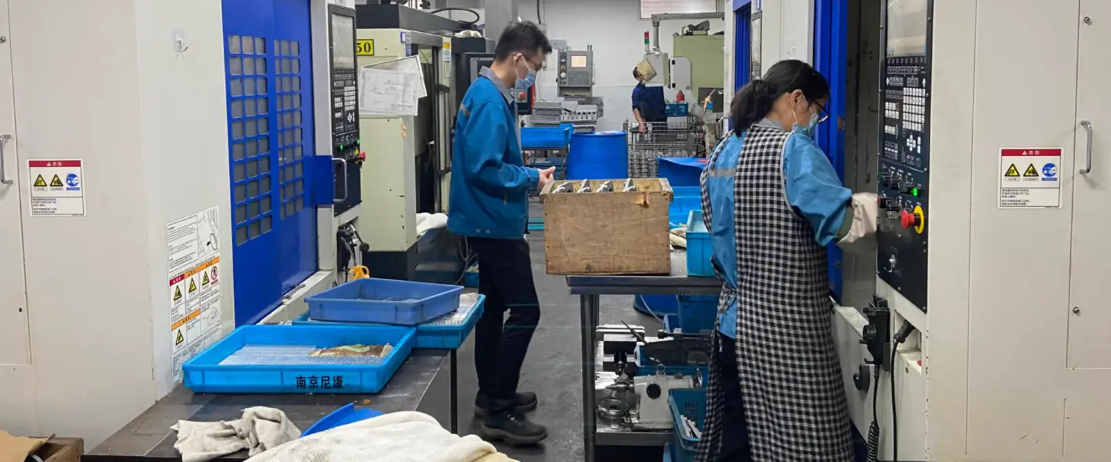
Lead Technical Image
Add a hero-level manufacturing, tooling, or component image that reinforces the article topic above the body copy.
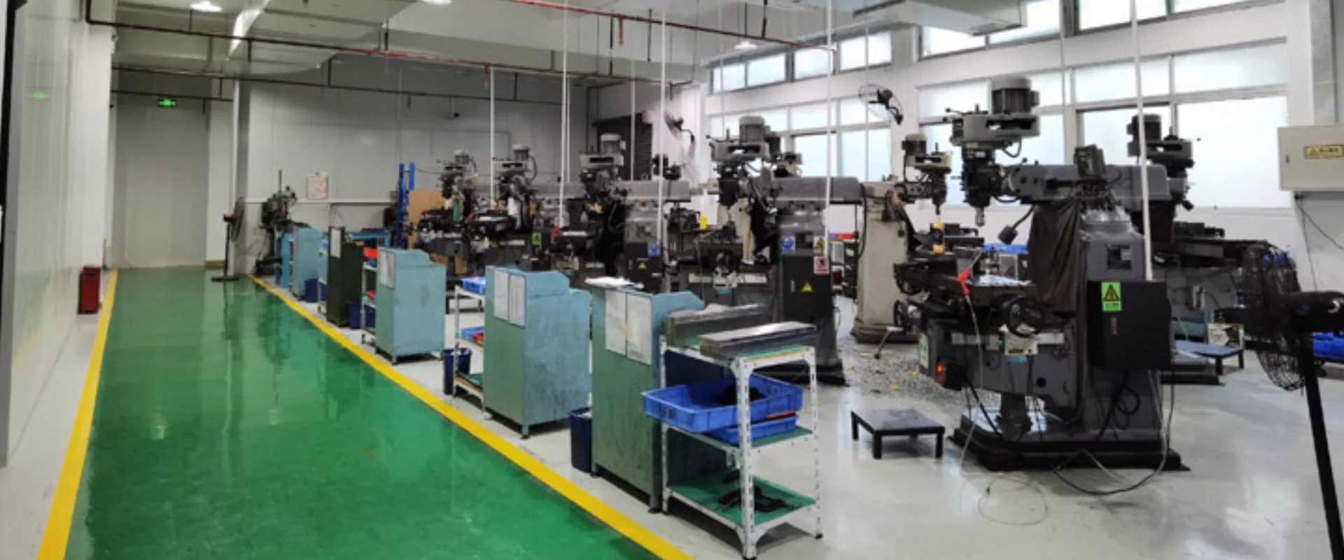
Comparison or Detail Image
Reserve a second image for an alloy comparison, defect example, tooling detail, or application close-up deeper in the article.
CNC machining die castings is used when as-cast geometry cannot meet functional tolerances, sealing requirements, bearing fits, threads, flatness, or assembly interfaces. Die casting creates the near-net shape; machining finishes the critical surfaces. For KastMfg's in-house capability — milling, drilling, boring, turning, and 5-axis machining in the same facility as the casting floor — see the die casting CNC machining service page.
The best cost result comes from machining only the features that need precision — every unnecessary machined face turns an efficient casting into an expensive hybrid part. This page gives a practical framework for deciding where machining belongs on the drawing: realistic as-cast tolerances, features that almost always need machining, datum strategy, and when to design the machining out entirely.
What As-Cast Tolerances Are Realistic
Die casting is a near-net-shape process, not a precision process. Before placing machining on a drawing, know what the casting alone can hold.
The NADCA Product Standards give the industry baseline for linear dimensions located within one die half: +/-0.25 mm on the first 25 mm, plus +/-0.025 mm for each additional 25 mm of dimension length. NADCA's precision grade tightens the first band to +/-0.05 mm. Dimensions that cross the parting line are looser again — die mismatch and flash add variation, and projected-area-based allowances of roughly +0.1-0.2 mm are typical.
In ISO 8062 terms, high-pressure die casting normally holds CT4-CT6. The total tolerance band by feature size:
| Nominal feature size (mm) | CT4 | CT5 | CT6 |
|---|---|---|---|
| Up to 10 | 0.26 | 0.36 | 0.52 |
| 10-16 | 0.28 | 0.38 | 0.54 |
| 16-25 | 0.30 | 0.42 | 0.58 |
| 25-40 | 0.32 | 0.46 | 0.64 |
| 40-63 | 0.36 | 0.50 | 0.70 |
| 63-100 | 0.40 | 0.56 | 0.78 |
Total tolerance band in mm per ISO 8062; divide by two for a bilateral +/- value. KastMfg's standard production tolerance is CT4-CT6. For a feature-by-feature look at what as-cast tolerances can hold, see die casting tolerances.
Two practical consequences for drawing markup:
- Any feature needing better than about +/-0.1 mm needs machining. As-cast, a 50 mm dimension carries +/-0.18-0.35 mm across the CT4-CT6 band.
- Geometric tolerances are the harder limit. Flatness, roundness, and position depend on die temperature balance and parting-line condition. As-cast flatness of 0.1-0.5 mm is realistic on small features, worse on large faces; as-cast aluminum runs Ra 1.6-3.2 um — fine for paint and assembly, too rough for static seals. For process-level detail, see our guide to die casting tolerances.
Features That Almost Always Need Machining
| Feature | Why Machining Is Needed |
|---|---|
| Bearing bores | Roundness, diameter, and alignment; as-cast bores are oval and draft-tapered |
| Sealing faces | Flatness and roughness; as-cast texture and parting-line flash cannot seal |
| Tight-pitch threaded holes | Cast holes are tapered and undersized; fine pitches cut poorly in softer alloys, so thread milling is often more stable |
| Gauge surfaces | Repeatable assembly and inspection reference |
| Gasket grooves | Controlled width, depth, and surface finish |
| Connector openings | Accurate fit and clean edges |
| Fluid ports | Leak-tight geometry and clean surface |
| Flatness-critical mounting faces | Warpage and parting-line mismatch beyond sealing limits |
Two rules of thumb:
- Cast pilot holes, finish by machining. A cored hole near final size, finished by boring or reaming, gives better location than drilling from solid and removes less stock.
- Cast the location, machine the thread. Coarse fastener holes are tapped after casting; fine-pitch or large-diameter threads are often thread-milled for stability. Never rely on an as-cast hole for a functional thread.
Datum Strategy: Machine From Datums, Not From Cast Surfaces
This decision wins or loses most of the machining cost on a part.
The common mistake is locating the casting off as-cast surfaces — a boss face, an outside wall, a cast rib. As-cast surfaces vary by tenths of a millimeter from part to part and cavity to cavity, so every machined feature inherits that variation. On a multi-setup part the effect compounds: each setup re-references a different unstable surface, and features drift relative to each other even when each setup holds locally. That is tolerance stack-up, and it arrives as assembly interference, fastener misalignment, and leak paths.
The fix is a deliberate datum chain:
- Designate cast datum features on the drawing — flat pads, bosses, or bores the die can form accurately and repeatably. Keep datums in one die half where possible, away from parting-line flash and ejector-pin marks.
- Machine the datum features first, ideally in a single setup.
- Reference every later operation from the machined datums. Once the part is located on its own machined datums, casting-to-casting variation stops entering the machined feature chain.
- State the scheme explicitly in GD&T. Do not leave fixture strategy to the supplier's discretion.
KastMfg's tooling and machining engineers select cast datum features and machining fixtures together at DFM review, so the datums the drawing calls out are the ones the die actually forms. Where no cast feature is stable enough, the first operation machines three mutually perpendicular reference surfaces (a 3-12-1 locating scheme) that all downstream work references.
Fixturing at Volume
Fixture cost should follow volume:
| Volume | Typical Approach | Why |
|---|---|---|
| Prototype / low volume | Machine vice with soft jaws | Soft jaws bored to grip finished features; cheap and quick to make |
| Medium volume | Soft jaws plus modular fixtures | Repeatable location with modest investment |
| High volume | Dedicated fixture per setup | Amortized over high volume; clamp sequence and force engineered in |
Two fixture rules protect dimensions:
- Never clamp on thin, flexible walls. A thin-wall casting springs under clamp load and springs back when the vice opens — correct in the fixture, wrong on the CMM. Clamp on ribs, bosses, or thick sections, and support the casting near the cut.
- Treat clamp force as a tolerance. Excessive force distorts the part during cutting; released, the metal relaxes and the surface goes out of flat. Production fixtures locate on datums and apply only enough force to resist cutting loads.
Cost Drivers
| Cost Driver | Why It Adds Cost |
|---|---|
| Number of setups | Every setup adds a fixture, handling time, and a CMM check; chip-to-chip time is the direct cost |
| Tolerance tightening | Tighter bands mean slower feeds, finer tools, temperature control, and 100% inspection instead of sampling |
| Deep or small holes | Tool wear, peck cycles, broken taps |
| Thin walls near cuts | Distortion under clamping, spring-back, slower conservative machining |
| Poor datum strategy | Rework, lot-to-lot inconsistency, assembly failures at the customer |
| Porosity near machined surfaces | Machining cuts below the skin and can open subsurface pores; critical zones need DFM review and, where leak tightness is mandatory, X-ray screening under our quality control process |
| Machining after coating | Masking, protection, and extra handling |
Two structural decisions dominate the quote: setup count and tolerance selection. Consolidating features so the part machines in two setups instead of four often saves more than negotiating any single tolerance. Each extra decimal place of tolerance carries measurable cost: a sealing face held to +/-0.02 mm machines and inspects very differently from one held to +/-0.1 mm.
When to Design the Machining Out
The cheapest machined feature is the one that never appears on the drawing. Before release, challenge each machined callout:
- Can the tolerance be relieved? If an as-cast +/-0.25 mm dimension still assembles and seals with a gasket, machining is pure added cost; many tight callouts exist only because drawing templates carry them by default.
- Can the feature be cast net-shape? Ribs, louvers, pockets, and locating bosses form well in the die; zinc alloys hold the finest as-cast detail of the three families (CT3-CT5, Ra 0.8-1.6 um), suiting visible hardware without post-machining.
- Can the function migrate? If a flatness-critical pad can move from a wide face to a small boss, the large face stays as-cast and only the boss is machined.
- Is the feature needed at all? Pilot holes, spot faces, and cosmetic chamfers accumulate cost quietly.
Removing machining pushes the requirement into the die instead — tolerances tighter than as-cast capability are achieved through die precision, so net-shape ambition belongs in tooling design, not in later drawing revisions. That trade-off between die investment and unit cost is covered in our die casting tooling cost guide.
Machining and heat treatment interact: the T5/T6 cycle can shift dimensions as internal stress redistributes, particularly through the T6 quench, so critical machined features and datums are normally finished after heat treatment. See heat treatment for the process options.
DFM Rules for Machined Die Castings
- Mark critical machined surfaces on the drawing — and leave everything else as-cast.
- Tighten tolerances only where function requires them.
- Leave stock on machined faces: typically 0.3-0.8 mm per side on aluminum die castings, up to about 1.5 mm on bores and sealing faces that must clean up shrink and draft variation.
- Put datums in one die half, away from flash and ejector pins.
- Clamp on ribs and bosses, never on thin flexible walls.
- Decide whether machining happens before or after surface finishing — and after heat treatment where applicable.
- Define burr limits for holes and edges.
- Protect machined faces during packaging and transit.
RFQ Checklist
Send the supplier:
- 3D model and 2D drawing
- Critical dimensions and the datum scheme (A/B/C references and GD&T)
- Tolerance and surface roughness requirements, separated by feature
- Thread specifications (pitch class, insert requirements)
- Annual volume and expected program life
- Surface finish requirements, including which features must be masked
- Inspection report requirements (FAI, CMM report, X-ray)
A machining quote is only as good as the drawing behind it. A drawing that distinguishes "machine this face" from "leave as-cast" gets an accurate price; a blanket tight-tolerance drawing gets a padded one. KastMfg runs die casting, CNC machining, inspection, and finishing coordination in one workflow and reviews datum strategy during DFM. Submit drawings through the RFQ page.
FAQ
Do all die castings need CNC machining?
No. Many non-critical surfaces remain as-cast; machining is reserved for functional features — bores, threads, sealing faces, gasket grooves, gauge surfaces, and datum pads.
What tolerance can CNC machining hold on die castings?
With sound datums and fixturing, general milled dimensions hold +/-0.05 mm; precision bores reach H6/H7 (+/-0.005-0.015 mm); ground sealing faces reach 0.01-0.02 mm flatness.
How much machining stock should be left on a die casting?
Typically 0.3-0.8 mm per side on faces to be milled, and up to about 1.5 mm on bores and critical sealing faces. Too little stock fails to clean up casting variation; too much wastes cutting time and clamping force.
Can machining expose porosity?
Yes. Machining cuts below the as-cast skin and can open subsurface porosity. Critical zones should be reviewed during DFM; where leak tightness is mandatory, X-ray or density-based sampling can be specified.
Does heat treatment affect machined dimensions?
It can. Solution treatment and quenching (T6) moves stress inside the casting and can shift dimensions, so critical features and datums are normally machined after the cycle.
How can buyers reduce machining cost?
Relax non-critical tolerances, machine only functional surfaces, design a clean datum chain, consolidate setups — and where possible design the feature out entirely by keeping it net-shape.
Related
About The Author
Mike Yao on machining die cast parts
Technical Director, Die Casting Engineering
Technical Director at KastMfg with 20+ years in high-pressure die casting, leading engineering and program management across aluminum, zinc, and magnesium programs for automotive, EV, electronics, and medical OEMs worldwide.
View author profileRelated Reading
Keep exploring the blog
Die Casting vs Permanent Mold Casting: Which to Choose?
Die Casting vs Permanent Mold Casting: How to Choose Die casting and permanent mold casting are both metal mold processes - both use reusable steel or iron dies rather than expe...
Mike Yao
8 min read
Landed Cost of Die Cast Parts from China: An RFQ Model
Landed Cost of Die Cast Parts from China: An RFQ Model Two quotations for the same die cast part can differ by a wide margin, and the lower number is not always the cheaper prog...
Mike Yao
12 min read
Can Steel Be Die Cast? Why Conventional HPDC Says No
Can Steel Be Die Cast? Why Conventional HPDC Says No No - steel cannot be made by conventional high-pressure die casting. The commercial process is limited to zinc, magnesium an...
Mike Yao
6 min read
Die Casting Design Guide: Rules, Tolerances & DFM
Die Casting Design Guide: Rules That Cut Cost and Improve Quality Good die casting design is the single biggest lever on part cost and quality - more than the alloy, more than t...
Mike Yao
5 min read