Threaded Holes in Die Cast Aluminum: Guide
How to design threaded holes in die cast aluminum: tapping vs inserts, form vs cut taps, engagement length, boss design against shrinkage, and RFQ thread callouts.

Technical Director, Die Casting Engineering
Blog Visual Plan
Article visuals for die casting threaded holes
These visuals use your current KastMfg image library now, and they will automatically switch to article-specific images when you add them later.
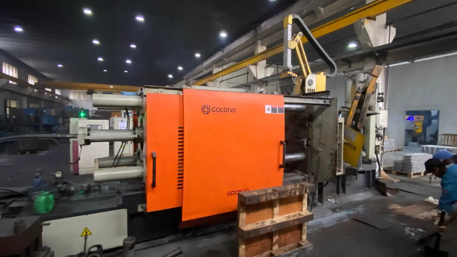
Lead Technical Image
Add a hero-level manufacturing, tooling, or component image that reinforces the article topic above the body copy.
Comparison or Detail Image
Reserve a second image for an alloy comparison, defect example, tooling detail, or application close-up deeper in the article.
Ask a machining forum whether threads can be tapped straight into die cast aluminum and the answers split into two camps. One calls it routine shop work; the other says no thread cut into cast metal deserves trust, and cites the M16 bolt that stripped its threads out of a die cast housing. Both camps report real outcomes: the difference is not the alloy's name but the condition of the metal around the thread — and in a casting, that is a design variable.
This guide is that decision logic: the threading question in as-cast material, three routes to a thread, form versus cut taps, engagement, boss design, zinc versus aluminum, and the RFQ. The principle throughout: a thread is anchored by the metal around it, and in a die casting that metal is something you engineer.
Threads in a Die Casting Are a Design Decision, Not a Default
The shorthand — "cast aluminum is weaker than 6061, so cast threads are weak" — states a verdict where there is only a conditional, with two parts.
The first is the as-cast condition: the alloy solidifies under pressure in a fraction of a second and ships in the condition the process gives it, without the working and aging that build ductility into a wrought temper. The workhorse alloys, compared in ADC12 versus A380, are chosen for castability, strength, and cost, and carry low elongation as-cast. That matters at a thread: a loaded flank passes force into the surrounding metal, and metal that cannot flow locally concentrates it on fewer flanks.
The second is local porosity. Gas and shrinkage voids are characteristics the aluminum die casting process manages rather than abolishes, and a void in a boss subtracts exactly the metal a flank needed. Detection has limits — castings have passed X-ray and still leaked, the porosity finer than the image could resolve — so porosity at a thread is handled by design (section 5), not caught by inspection.
The strength of a die cast thread is therefore an outcome of four variables: the alloy and its condition, the quality of that casting, the geometry around the hole, and the load the joint carries. A drawing that treats threading as a default hands all four to chance.
Three Routes: Tap the Casting, Install an Insert, or Machine the Thread
Every threaded hole in a die casting arrives by one of three routes, chosen by the joint's service and loads, not habit.
Tap the casting. The die cores a hole slightly undersize of the drill; machining opens it to tap size and cuts the thread. It is the cheapest route per hole — one setup, standard tooling, no added component — and fits joints assembled once and left alone. Its limit is service: a cut thread in as-cast material is the joint described above, so it earns the discipline of sections 4 and 5.
Install a threaded insert. An insert places a hardened steel or stainless thread where the casting's own would be the weak link, in three families: helical-coil (wire-thread) inserts wound into an oversize tapped hole; solid or thin-wall bushings pressed or threaded in; and cast-in inserts set into the die so the alloy forms around them. They earn the added part and installation step where the joint is opened repeatedly or serviced in the field, or where loads are high or cyclic.
Cast the hole, machine the thread. For large threads, tight positional or class requirements, or the most critical joints, the cored hole is cast with machining allowance and the thread is thread milled or single-pointed on the machining center rather than tapped. It tops the precision and cost range and leans hardest on the CNC machining side of the program.
One constraint deserves its own paragraph: small threads. Below roughly M3, making the thread and making it strong both get harder — core pins have a practical minimum, small taps are fragile in anything but sound metal, and a small pitch diameter leaves little flank area in a lower-ductility casting. That pushes designers toward inserts, but it is pressure, not law: the same four variables decide, and no size makes inserts mandatory.
Form Taps vs. Cut Taps: Ductility Decides
A cut tap removes metal to open the thread; a form tap rolls the profile into the hole wall, displacing metal instead of cutting it. Shop experience reports formed threads holding better in castings; the metallurgy is real but conditional: in a ductile alloy, a formed flank carries a work-hardened, uninterrupted grain flow instead of severed grains, and the process leaves no chips to pack a blind hole or lodge in porosity.
The condition is the word ductile. Forming works only where the material flows, and the common die cast aluminums sit at the low end of the elongation range; a form tap meeting locally porous or brittle metal can leave a rolled but weakened flank. Form tapping can therefore give a stronger thread in a die casting, and it is not a universal recommendation for low-ductility alloys such as A380 and ADC12. The conservative sequence: cut tap by default, form tap where the alloy's ductility and that casting's quality are demonstrated on production parts from the actual tool.
Two details complete the decision: a formed thread needs its own pre-hole diameter, larger than a cut tap's drill size, so the hole is specified for the process; and switching between cut and form tapping is a process change, not a drop-in substitution — so it belongs in the RFQ, not shop-floor discretion.
How Much Thread Engagement to Specify
The engagement numbers engineers quote are rules of thumb, useful as long as they stay labeled: roughly one diameter of engagement in steel, and one-and-a-half to two diameters in aluminum. The aluminum figure is shorthand for "the housing is weaker than the fastener, so give the load more flanks to share," and the honest version continues with the dependencies: fastener grade, alloy and condition, static versus cyclic loading, boss quality. A die cast boss as-cast can sit below the wrought-aluminum assumption behind the shorthand, so the conservative review for a critical joint is upward — toward more engagement.
A second rule circulates alongside: a joint reaches full strength at about eight engaged threads, the first threads carrying most of the load. Treat it as what it is — an old shop rule from stiff nut materials. In a weaker housing, engagement does different work: spreading load across enough flank area that the housing thread is not the failure mode.
What the drawing should carry is the requirement, not the folklore: minimum full-thread depth rather than drill depth, engagement per hole for critical joints, and — in blind holes — depth for tap lead-in and chip clearance.
Boss Design: Where Shrinkage Meets the Thread
Most stripped threads in die cast parts are not thread-form failures; they are porosity failures wearing a thread's shape. The mechanism is thermal: a solid, heavy boss is a mass inside thinner wall, it solidifies last, and where surrounding metal cannot feed it, it feeds itself with voids — shrinkage porosity parked exactly where the flanks will anchor. Machining the cored hole opens the porosity to the surface, and the thread gauges correctly while carrying a fraction of what the boss implied.
The prevention is established design practice: uniform wall thickness around the boss, so no local mass outlasts its neighbors; generous fillets where boss meets wall; cored-out (hollow) bosses where a section would run thick, holding mass near nominal wall; and gate and feeding placement agreed with the caster so the boss is not last to solidify with nowhere to draw from. For how the porosity forms, see die casting gas porosity; the rules above are its thread-specific application.
Two callouts complete the boss: enough outer-diameter metal that flanks anchor in material rather than the boss-to-wall transition, and a cored hole with diameter and tolerance that leave a controlled, repeatable tapping allowance — cored-hole accuracy sits inside the wider die casting tolerances picture.
Zinc vs. Aluminum for Threaded Features
Everything above is written in aluminum's voice, because aluminum is where the question gets asked. Zinc die casting changes the inputs: the Zamak-family alloys run noticeably more ductile than the common die cast aluminums, and ductility is the property this whole discussion turns on.
The differences show up three ways. Form tapping is more often viable, for the same grain-flow reason. As-cast threads enter the option space: zinc fills fine detail faithfully, and threads are sometimes cast rather than machined, deleting an operation the aluminum version pays for. And small threaded features in zinc are frequently successful — an observation that must stop short of a rule. "Smaller threads are more reliable in zinc" is not a law; the same four variables still decide, and a starved zinc boss strips like any other. Zinc widens the option space; it does not repeal the design work.
Aluminum's counterpart: as-cast threads are seldom the default — the standard practice is a cored or drilled hole and a machined thread — while aluminum keeps the strength, stiffness, and weight position that make it the default housing material.
What the Die Caster Needs in the RFQ
A threading RFQ that ends well hands the die caster five blocks of specifics.
A thread schedule. Every threaded hole as a line item: nominal size and pitch, tolerance class, through or blind, cored or drilled, drill depth, minimum full-thread depth, and the engagement requirement for critical joints. A face that says only "M6" is asking the caster to quote assumptions.
The insert definition. Where inserts are used: type and part number — the helical-coil or solid-bushing standard the design calls up — cast-in versus post-installed, the installation method and hole preparation, and who supplies and who installs. Cast-in inserts belong in DFM before tooling is committed; discovering them at first article is expensive for both sides.
Boss geometry and tolerances. Boss outer diameter, cored-hole diameter with tolerance, position to datums, fillets, and wall transitions — where section 5's prevention becomes enforceable; specified geometry is cheaper than renegotiated first articles.
The machining split. Which threads the caster produces and which arrive as cored or drilled holes for your side, plus the sequence relative to finish — a coating over a thread changes its effective size, so masked, cut-after-coating, or re-tapped threads belong in the plan.
First-article verification. How threads will be proven: GO/NOGO gauge inspection per hole at first article and on an agreed sampling basis in production, plus torque or pull-out testing on samples for critical joints, against an acceptance value from your design authority rather than the caster's discretion.
FAQ
What is the smallest practical thread in die cast aluminum?
There is no universal floor. The constraints stack — core pins have a practical minimum, small taps are fragile, and a small pitch diameter leaves little flank area in a lower-ductility casting — and they bite harder below roughly M3, but they stay design-dependent. Whether a small thread is tapped directly or carries an insert is decided by the alloy, the boss quality behind it, and the load — not by a size cutoff.
Does a joint opened repeatedly need an insert?
Inserts are the standard answer for high-cycle, serviceable joints: a hardened steel thread shrugs off cycles that wear aluminum flanks. "Need" is stronger than the evidence — bare aluminum threads do not inevitably degrade, and how fast they wear depends on assembly technique, torque control, lubrication or anti-seize, the load, and the number of cycles. A joint opened twice a year with controlled torque can outlive the product on tapped threads; one opened weekly in a corrosive environment is an insert candidate.
Can a threaded insert repair a thread that failed in the field?
Often, yes: restoring a stripped hole with a helical-coil insert, drilled and tapped oversize, is one of the oldest field repairs in metalworking, and legitimate for a casting. Two cautions bound it: the repair needs sound metal and wall around the oversize thread — a thin or porous boss limits what is repairable, and a second failure may end the part. And an insert repairs the thread, not the joint's foundation: it gives a steel-grade internal thread, but the anchor is still the surrounding casting, and under sufficient load the casting — not the insert — can still fail first. A field repair restores function; a repeating failure is a redesign signal.
Why do threads strip so easily in zinc die cast parts — and how do I fix or prevent it?
Because the material ladder is stacked against the boss. Zamak 3 yields around 220 MPa; a Grade 2 steel bolt is stronger than the zinc it threads into, so an under-designed zinc boss is the sacrificial part of the pair by design. Repair follows the wall you have left. A helical-coil insert needs an oversize STI tap, and in a thin-wall zinc housing that tap can eat most of the remaining wall — the classic complaint from repair threads is "after tapping for the Helicoil, the wall is too thin." Where wall rules the coil out, the reported field routes are solid-bushings-style inserts (Time-Sert class, which needs less wall than a coil), epoxy-mounted studs, and retaining-compound repairs for lightly loaded joints — practitioner solutions rather than standards, so treat them as fit for non-critical service and validate against the load. Prevention is cheaper and numeric. A quoted working set for thread-forming screws in a zinc boss: for an 8-32 tri-lobular screw, pilot hole around 0.148", minimum boss diameter around 0.272", and thread engagement around 2× the screw diameter (one program's figures, not a standard — your alloy, screw type, and cycles govern). The general rules of thumb: engagement near 2× diameter, a boss generous enough to put sound metal around the full thread, form-rolled screws rather than cutting screws in ductile zinc, and cast-in or pressed inserts for serviced joints. One corrosion trap worth knowing at design time: brass inserts in electrical contact with zinc form a galvanic pair in which the zinc is the anode — in wet service the boss corrodes around the insert. Steel or stainless inserts are the safer pairing there.
Self-tapping screws, tapped threads, or inserts — which should I choose for a die cast aluminum part?
Send Your Threading RFQ to KastMfg
KastMfg is a China-based (Nanjing) die casting manufacturer producing aluminum, zinc, and magnesium high-pressure die castings, with in-house tooling, CNC machining, and DFM review with every quote. Threaded features are engineered on your drawing — boss geometry, the tapping and insert plan, first-article gauge inspection — and reviewed before tooling is committed. To receive a quotation grounded in your real threading scope, submit:
- CAD model (STEP/STP) and PDF drawing with revision, including the thread schedule and boss callouts
- Alloy requirement
- Annual volume and expected program life
- Key dimensions and critical-to-thread features: thread sizes and classes, depths, engagement, boss geometry
- Surface finish, including masking or post-coating threading of coated parts
- Testing requirement: first-article GO/NOGO gauge inspection plus any torque or pull-out testing and its sampling plan
- Destination country and delivery term
Send your package through the request a quote page or email it to casting@kastdiecast.com.
KastMfg Manufacturing Co., Ltd. Email: casting@kastdiecast.com | Phone: +86 138 1403 4409 No.6, Rungu Road, Nanjing, China
Related
About The Author
Mike Yao on die casting threaded holes
Technical Director, Die Casting Engineering
Technical Director at KastMfg with 20+ years in high-pressure die casting, leading engineering and program management across aluminum, zinc, and magnesium programs for automotive, EV, electronics, and medical OEMs worldwide.
View author profileRelated Reading
Keep exploring the blog
Die Casting Design Guide: Rules, Tolerances & DFM
Die Casting Design Guide: Rules That Cut Cost and Improve Quality Good die casting design is the single biggest lever on part cost and quality - more than the alloy, more than t...
Mike Yao
5 min read
Aluminum vs Zinc Die Casting - How to Choose
Aluminum vs Zinc Die Casting — Choosing the Right Material for Your Part Aluminum and zinc are the two dominant die casting metals globally, together accounting for over 90% of...
Mike Yao
5 min read
Die Casting vs Permanent Mold Casting: Which to Choose?
Die Casting vs Permanent Mold Casting: How to Choose Die casting and permanent mold casting are both metal mold processes - both use reusable steel or iron dies rather than expe...
Mike Yao
8 min read
Can Steel Be Die Cast? Why Conventional HPDC Says No
Can Steel Be Die Cast? Why Conventional HPDC Says No No - steel cannot be made by conventional high-pressure die casting. The commercial process is limited to zinc, magnesium an...
Mike Yao
6 min read