Fillet vs Chamfer - Which Edge Treatment for Cast and Machined Parts
Fillet vs chamfer compared for die cast and machined parts: stress concentration, metal flow, die life, machining cost, and how to call each out on a drawing.

Technical Director, Die Casting Engineering
Blog Visual Plan
Article visuals for fillet vs chamfer
These visuals use your current KastMfg image library now, and they will automatically switch to article-specific images when you add them later.
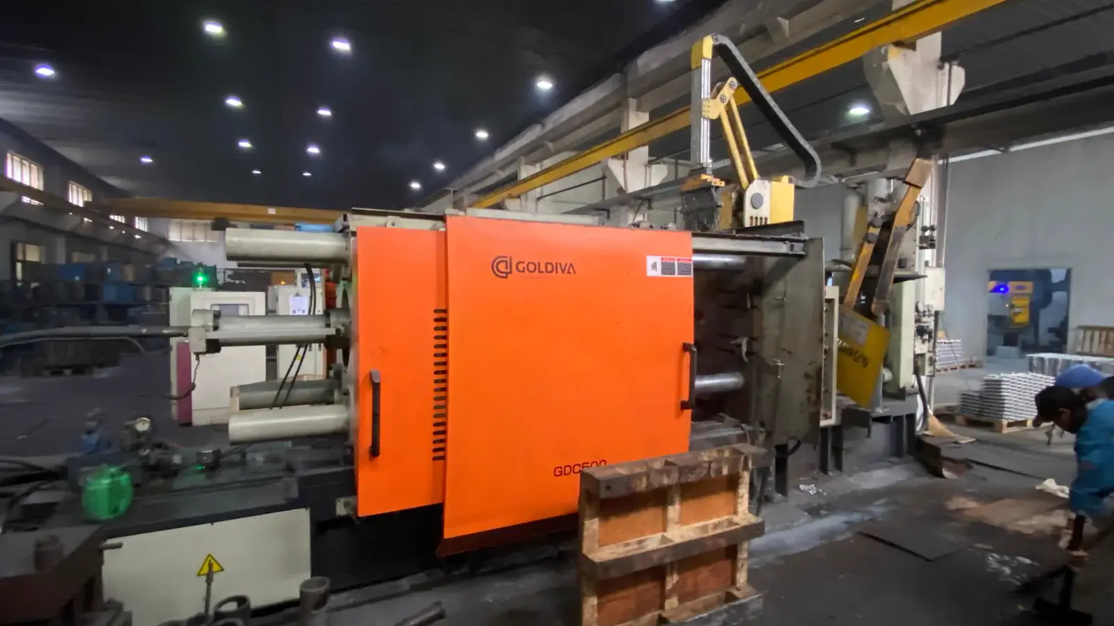
Lead Technical Image
Add a hero-level manufacturing, tooling, or component image that reinforces the article topic above the body copy.
Comparison or Detail Image
Reserve a second image for an alloy comparison, defect example, tooling detail, or application close-up deeper in the article.
Every drawing eventually has to deal with sharp corners, and the two tools for that job are the fillet and the chamfer. Both remove the sharp edge - but they do it for very different reasons. A fillet is a structural and process feature: a rounded transition between two surfaces that controls stress and helps metal flow and solidify. A chamfer is an edge treatment and assembly feature: a flat, angled face that removes burrs, protects hands, and guides parts together.
So which one belongs on your part? If you search "fillet vs chamfer" or "chamfer vs fillet" hoping for one universal answer, here it is up front: on a die casting, internal corners almost always get fillets. On machined edges and assembly interfaces, chamfers usually win. The rest of this guide explains why, with numbers, drawing callouts, and decision rules.
Fillet vs Chamfer at a Glance
| Factor | Fillet | Chamfer |
|---|---|---|
| What it is | Rounded (tangent) transition between two faces | Flat angled face, commonly 45 degrees |
| Drawing callout | Radius: R2, R2.0 +/-0.2, 2X R1.5 | Distance x angle: 1 x 45 deg, or 1 x 1 |
| Primary purpose | Stress control, metal flow, die life | Deburring, safety, assembly lead-in |
| Stress behavior | Single tangent line, low stress concentration | Two sharp intersection lines remain |
| Typical location | Cast internal corners, rib roots, boss roots | Machined edges, holes, shafts, cast outer edges |
| Cost tendency | May need ball end mills or specific radius tools | Usually one pass with standard tools |
Why Castings Need Fillets
A sharp internal corner in a die casting is a problem four times over:
- Metal flow. Molten metal filling the cavity slows down and swirls at sharp corners. Rounded corners let the metal flow smoothly, reducing cold shuts and trapped air.
- Solidification stress. Metal shrinks as it solidifies. A sharp corner is where hot and cold sections meet, and it concentrates solidification stress - a prime site for hot cracking.
- Stress concentration in the part. Under load, a 90-degree internal corner multiplies local stress (numbers below). A radius spreads it out.
- Stress concentration in the die. The same geometry concentrates thermal stress in the die steel at every cycle. Sharp die corners are exactly where heat checking and early die failure start.
For starting values, NADCA-derived guidelines often cite roughly 1.5 mm as a minimum internal fillet for aluminum die casting, with about 3.5 mm as a general-purpose radius; other guidelines scale the minimum radius to wall thickness, around R min = 0.5t + 0.25 mm, with internal corners starting near 0.75 mm. Treat these as starting guidelines, not universal standards - the right radius depends on wall thickness, load, and the die.
Stress Concentration in Numbers
Stress concentration is the ratio Kt = peak local stress / nominal stress. The values below are illustrative values, geometry-dependent - use them to understand the trend, and verify final designs with charts or FEA.
| Internal corner geometry | Approximate Kt |
|---|---|
| Sharp 90-degree corner | 2.5-3.0+ |
| Small fillet (r/d = 0.05) | 1.8-2.0 |
| Medium fillet (r/d = 0.10) | 1.4-1.6 |
| Generous fillet (r/d = 0.20) | 1.2-1.3 |
| 45-degree chamfer | 1.5-2.0 |
Two takeaways. First, any radius beats a sharp corner, and a generous radius beats a small one. Second, a chamfer is better than a theoretical sharp corner, but its two intersection lines still carry stress concentration. For fatigue-loaded internal corners, choose a fillet - and back it up with a stress chart or FEA rather than guessing.
Why Machined Parts Get Chamfers
Machined parts live a different life than castings, and chamfers fit that life:
- Deburring. Every machined edge leaves a burr. A chamfer breaks it off cleanly in the same setup.
- Safety. Chamfered edges do not cut hands during assembly and handling.
- Assembly lead-in. Shafts, pins, seals, and threaded fasteners start easily against a chamfer. This is the main functional reason chamfers appear on mating parts.
- Centering. A chamfer gives a countersink or pilot a place to seat, helping concentric starts in drilling and tapping.
- Tool economy. A chamfer is one pass with a chamfer mill, spot drill, or turning tool. A controlled small fillet on a machined part often needs a ball end mill, extra toolpaths, or a dedicated radius tool.
Note the "usually" in that last point. Chamfers are generally cheaper to machine than tight, controlled radii - but not always. Cost depends on tool access, machine type, and tolerance. A loose chamfer is cheap; a chamfer held to +/-0.05 mm is not.
Cost: Chamfer vs Fillet - It Depends Where
The cost question has two very different answers depending on which side of the process you stand on.
Machined parts. On a CNC-machined part, chamfers usually win. One chamfer tool, one pass, done. Small precision fillets may require ball end mills, multiple passes, or special radius tools, and the tool wear shows up on tight radii first. If the function is deburring or lead-in, a chamfer is the economical call.
Die casting tooling. Here the argument flips. Inside the cavity, corners functionally need fillets: smoother metal flow, lower stress in the die steel, longer die life. Cutting a chamfer into a die core might save a few minutes of machining time, but a chamfered corner inside the cavity leaves two sharp intersection lines - exactly where heat checking starts - and the small machining time difference is overwhelmed by die life and casting quality gains. Die feature cost really depends on accessibility, cutter reach, EDM work, and polishing, not on "chamfer cheap, fillet expensive."
Drawing Callouts
Call each feature the way the shop expects to see it:
- Fillet: a radius callout. Examples: R2 (one corner), R2.0 +/-0.2 (tolerance), 2X R1.5 (two matching corners).
- Chamfer: distance x angle. Example: 1 x 45 deg. Or double setback: 1 x 1, which implies 45 degrees when both distances are equal.
- Break edges note: a blanket shop note such as "Break all sharp edges 0.2-0.5 mm unless otherwise specified." This is a common shop and drawing convention - it covers the edges nobody bothered to dimension.
Use the break-edges note with care. It must not override features that are already specifically dimensioned: a fillet called out as R1.5 stays R1.5, and sealing edges or press-fit edges may need edges left sharp - or call those out explicitly so the blanket note does not eat them. Deburring convention is typically a 0.2-0.5 mm chamfer at 45 degrees or an equivalent small radius; that is a workshop convention, not a universal standard.
Decision Rules
Use these as a quick filter, then confirm against your load case and drawing:
- Die casting internal corner (rib root, wall junction, boss root): fillet. Never leave a sharp internal corner in a casting.
- Machined external edge, deburring, or assembly lead-in: chamfer.
- Fatigue-loaded internal corner: fillet, sized from a stress concentration chart or FEA - do not guess.
- Sealing face or press-fit edge: follow the drawing's specific requirement; do not let a blanket break-edges note modify it.
- Cast external cosmetic edge: a small chamfer or radius, per your cosmetic standard.
- Either feature where a tool cannot reach: redesign the feature, not the tolerance - talk to your foundry or machine shop before release.
Frequently Asked Questions
Is a chamfer cheaper than a fillet?
On machined parts, usually - a chamfer is one pass with a common tool, while a tight controlled radius may need a ball end mill or special tool. On die casting tooling, the question barely applies: internal die corners need fillets for flow and die life, and any small machining time saved by chamfering is lost to earlier die failure. Cost always depends on accessibility, tooling, and tolerance, not just geometry.
Can I use chamfers on a die casting?
Yes - on external edges. A small chamfer or rounded edge on the outside of a casting is standard for handling and deburring. What you should not do is leave sharp internal corners in the cavity: internal junctions belong as fillets, because a chamfer inside the cavity still leaves two sharp intersection lines where stress concentrates in both the casting and the die.
What radius should I use on a die cast part?
Start from NADCA-derived guidelines - around 1.5 mm minimum internal fillet for aluminum die casting, or roughly R min = 0.5t + 0.25 mm scaled to wall thickness - and treat them as starting points. Increase the radius at rib roots, boss roots, and highly loaded corners, and confirm critical locations with stress analysis. The fuller answer lives in our die casting DFM guide.
What does "break all edges" mean?
It is a blanket drawing note telling the shop to remove every sharp edge, typically with a 0.2-0.5 mm chamfer at 45 degrees or an equivalent small radius, unless a specific edge is dimensioned otherwise. It does not replace individually called-out fillets, and it should not be applied where a sharp or specific edge is required - call those out explicitly.
Fillet or chamfer for a cosmetic edge?
Either works on an external cosmetic edge, and the choice is usually cosmetic or process-driven. A radius looks and feels softer; a chamfer reads crisper and is cheaper to machine. On cast parts the edge is formed by the die either way, so pick the look you want and put it on the drawing - the die will reproduce it every cycle.
Related Reading
- die casting DFM guide - full design-for-manufacturability review process
- die casting design guide - buyer-focused design overview
- die casting draft angle guide - draft pairs with radii on every wall
- die casting tolerances - how radius callouts interact with tolerance stacks
- die casting hot shortness - why sharp corners invite hot cracking, the sister page to this one
Have a drawing full of sharp internal corners? Send it to casting@kastdiecast.com - our DFM review marks every corner that needs a radius before tooling | +86 138 1403 4409 | No.6, Rungu Road, Nanjing, China
About The Author
Mike Yao on fillet vs chamfer
Technical Director, Die Casting Engineering
Technical Director at KastMfg with 20+ years in high-pressure die casting, leading engineering and program management across aluminum, zinc, and magnesium programs for automotive, EV, electronics, and medical OEMs worldwide.
View author profileRelated Reading
Keep exploring the blog
CNC Machining Die Castings: Tolerances & Cost
CNC Machining Die Castings - When It Is Needed, Tolerances and Cost Impact CNC machining die castings is used when as-cast geometry cannot meet functional tolerances, sealing re...
Mike Yao
8 min read
Landed Cost of Die Cast Parts from China: An RFQ Model
Landed Cost of Die Cast Parts from China: An RFQ Model Two quotations for the same die cast part can differ by a wide margin, and the lower number is not always the cheaper prog...
Mike Yao
12 min read
As-Cast Surface Finish: What Die Castings Really Look Like
As-Cast Surface Finish: What Die Castings Really Look Like "As-cast" is the surface a die casting carries the moment it leaves the die and the trim press - no blasting, polishin...
Mike Yao
8 min read
Can Steel Be Die Cast? Why Conventional HPDC Says No
Can Steel Be Die Cast? Why Conventional HPDC Says No No - steel cannot be made by conventional high-pressure die casting. The commercial process is limited to zinc, magnesium an...
Mike Yao
6 min read