X-Ray Passed But Part Failed: E155 vs SDAS
Parts can pass ASTM E155 die casting X-ray grades and still fail in service. Why radiography blind spots and SDAS miss risk, and what to specify instead.

Technical Director, Die Casting Engineering
Blog Visual Plan
Article visuals for ASTM E155 die casting
These visuals use your current KastMfg image library now, and they will automatically switch to article-specific images when you add them later.
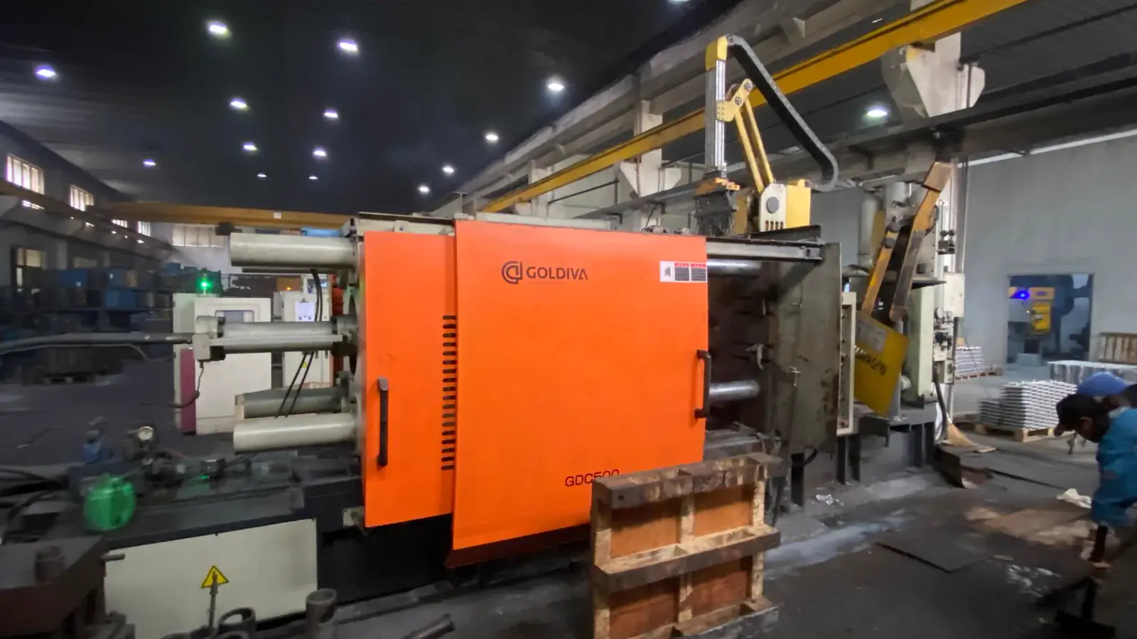
Lead Technical Image
Add a hero-level manufacturing, tooling, or component image that reinforces the article topic above the body copy.
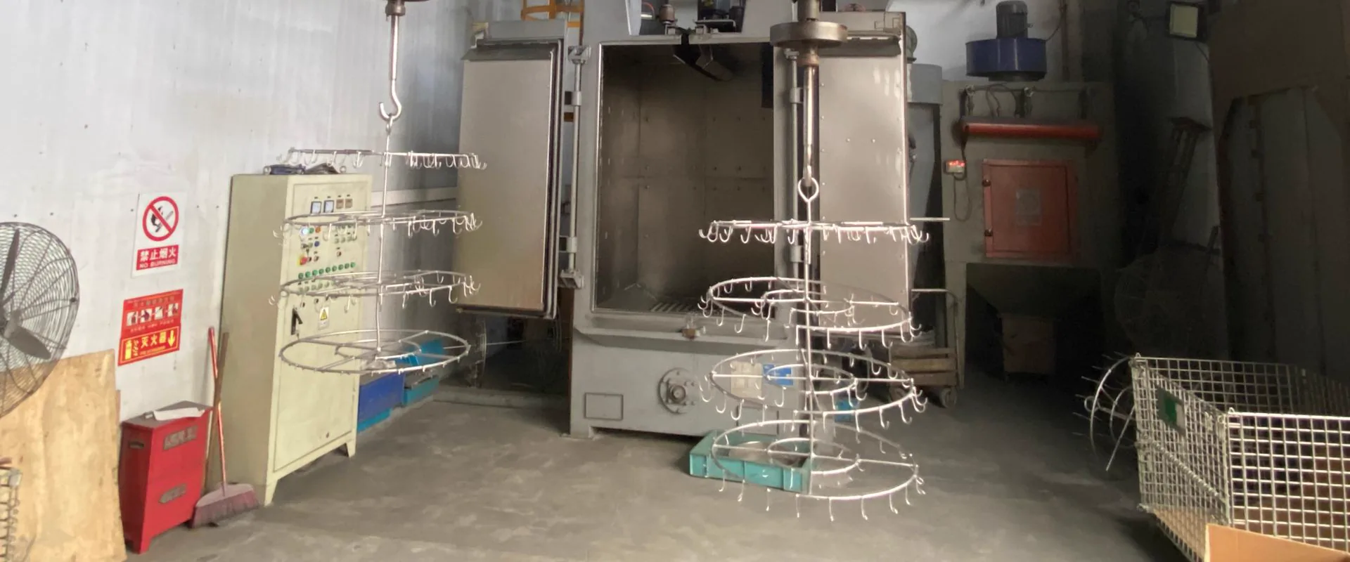
Comparison or Detail Image
Reserve a second image for an alloy comparison, defect example, tooling detail, or application close-up deeper in the article.
A familiar pattern in die casting quality disputes: the drawing carries a radiography note — a reference standard and a severity level. First-article films come back graded within the called level. Production ships. Then a bracket cracks on the test bench, a housing weeps at a thick boss under pressure cycling, or tensile coupons from a supposedly good lot show elongation far below expectation. The supplier opens the film archive and every image is within spec. The buyer holds the failed part. Nobody is lying; the two documents are answering different questions.
That difference is the subject of this article. A radiography note asks: do these projections show discontinuities above a defined severity, compared with reference images? It says nothing about features too small for the image to resolve, and nothing about how the metal solidified — which is what largely determines whether a part can carry load. A casting can be radiographically clean and mechanically weak at the same time.
The sections below sort out which reference standard actually applies to die castings, where radiographic grading stops, what secondary dendrite arm spacing (SDAS) is and why no X-ray sees it, and how to convert all of that into drawing language, acceptance steps, and RFQ questions. It is written for sourcing and supplier-quality teams responsible for aluminum die casting programs — not for radiographers.
What E155 Covers — and Why Die Castings Are Graded Against E505
ASTM E155 is one of the most-cited reference radiograph standards in metalcasting, and it is routinely cited for the wrong castings. Its reference radiographs illustrate the types and degrees of discontinuities found in aluminum-alloy and magnesium-alloy castings produced by general casting processes. Its images reflect the solidification behavior of sand and permanent-mold-type castings — heavier sections, slower cooling, and discontinuity forms to match.
High-pressure die castings solidify under very different conditions: extreme cooling rates, intense feeding from the gate, and gas and shrinkage distributions specific to the process. Grading them against images from another process family makes every call an act of interpretation. The counterpart standard for them is ASTM E505, whose reference radiographs cover aluminum and magnesium alloy die castings specifically; severity is expressed in grades — commonly cited grades 1 through 8 for gas porosity and shrinkage — and automotive-style drawings typically call a maximum grade per zone. How the inspection methods compare in practice is covered in the existing guide to die casting porosity testing; the point here is only which book you are grading from.
| ASTM E155 | ASTM E505 | |
|---|---|---|
| Scope | Aluminum and magnesium alloy castings, general casting processes | Aluminum and magnesium alloy die castings |
| Provides | Reference radiographs of discontinuity types and degrees | Reference radiographs of die casting discontinuity categories and severity |
| Where it fits | Sand and permanent-mold-type aluminum castings | High-pressure die castings graded by zone |
Drawings for die-cast aluminum parts that cite E155 are common enough that many suppliers quietly grade against die casting reference images anyway — and then the argument has two standards in it. The consequences are predictable: severity calls disputed because the reference images do not represent the process, and an audit finding on a drawing that cites a standard outside its scope. If the intent is "die castings, graded by reference radiographs," write the die casting standard — or your customer's equivalent — on the drawing.
What an X-Ray Grade Does — and Does Not — Tell You
Setting aside which standard is called, radiographic grading itself has three structural blind spots.
A radiograph is a shadow, not a map. Production radiography projects the entire thickness of the part onto one image. Features at different depths superimpose; a scatter of small pores can blend into a gray patch or hide behind a change of section; apparent severity shifts with projection angle. Multiple projections reduce the ambiguity, but every image still integrates a whole thickness. Grading is comparative judgment of an image against a reference image — not a count, and not a measurement, of what is inside the part.
What is below the resolution simply does not appear. An imaging chain resolves features at a scale set by the source, the geometry, and the detector. Distributed micro-porosity — exactly the population that matters for fatigue behavior and for sealing after machining — can sit beneath what production radiography shows. The film is not wrong; it describes a part in which nothing visible exceeds the called severity. Fine porosity the technique cannot see still exists and still matters. Where that gas comes from, and how it is prevented at the machine, is a process question covered in the guide to gas porosity in die castings.
A grade rates severity, not consequence. The same discontinuity at the same severity is harmless in a low-stress rib and decisive at a machined sealing face, a fillet under cyclic load, or the center of a thick boss. Unless the drawing zones the part, a single called grade merges those cases into one verdict. And no radiograph, at any grade, says anything about whether a machined circuit will hold fluid — that question belongs to leak testing, compared in helium leak testing versus pressure decay.
A passed grade is therefore a real and useful result — the projections examined showed nothing above the called severity — and it is not a prediction of mechanical performance. The other half of the story, the part's solidification structure, never appears on film at all.
SDAS: The Solidification Metric Radiography Cannot See
As a casting solidifies, the alloy grows tree-like crystals — dendrites — with secondary arms branching off a primary trunk. The center-to-center spacing between neighboring secondary arms is the secondary dendrite arm spacing. That spacing is a physical record of how fast heat was extracted locally: where cooling is fast, the arms are fine and closely spaced; where a thick section or a hot spot cools slowly, the arms are coarse and widely spaced. And the spacing pays forward into properties. A fine structure shortens diffusion paths, improves feeding between the arms, and distributes second phases on a finer scale — measured tensile strength, elongation, and fatigue resistance all improve as SDAS decreases. A coarse-SDAS zone is, mechanically, the soft spot where failure initiates.
Radiography cannot see this, for two independent reasons. The first is scale: in high-pressure die castings, SDAS values in typical published ranges run on the order of single-digit to a few tens of micrometers, coarser in thick sections — far below what production radiography, and production CT, resolve. The second is contrast: dendrite arm spacing is not a void. It produces no density difference for X-rays to catch, because it describes how the solid metal is arranged, not what is missing from it. Radiography detects absence; SDAS describes architecture.
This is why a part can pass its radiography level and still fail under mechanical stress. No visible porosity with coarse structure: the film is clean and the boss is weak. Modest fine porosity with fine structure: the film looks worse and the part performs. The film cannot rank those two parts against each other; a polished section under a microscope ranks them instantly. If your acceptance system contains only radiography, solidification structure is simply outside its field of view.
SDAS depends on the alloy and on the section, so any target travels with the design. For context on the two most common aluminum die casting alloys, see ADC12 versus A380.
What to Specify on the Drawing Instead of a Bare Radiography Note
Keep the radiography note — zoned and pointed at the right standard. What protects the mechanical side is adding structure to the acceptance system, in three moves.
Zone the radiography call correctly. Grade the die casting against the die casting standard (E505-style references for aluminum and magnesium die castings, or the customer equivalent), define critical zones on the drawing, and call a maximum grade per zone together with the projections required to see them. The mechanics of writing that note are laid out in the guide to porosity testing and acceptance criteria.
Add destructive verification for structure-critical features. Where a thick, load-bearing, or fatigue-critical section exists, write a metallographic clause: at first article, a defined number of parts — commonly one per tool cavity — is sectioned through the critical feature, prepared and etched, and SDAS is measured by optical metallography at a stated magnification, with micrographs and measurements reported against an agreed limit or an approved baseline. Repeat at defined intervals and at process-change triggers: tool modifications, cavity changes, anything that alters local cooling. Be honest about sampling: a coupon cut from an overflow tells you about the overflow. Where the part allows it, section the real feature, or agree on a coupon whose solidification history tracks it. Then retain the approved micrographs as the program baseline, so later disagreements compare structure against structure rather than adjective against adjective.
On cost: this is a routine commercial-laboratory service priced per sample — commonly tens to low hundreds of US dollars — noise against a structural field failure. On the limit itself, do not lift a number from a chart: typical published SDAS ranges for high-pressure die castings (roughly 5-25 µm, alloy- and thickness-dependent) describe the process, not your part. A defensible limit comes from the design authority, from a validated correlation between SDAS and properties, or from the approved first article.
Negotiate cooling-rate control, not porosity adjectives. "Low porosity" is a promise about an outcome; a cooling condition in a named zone is a process parameter a supplier can engineer. Ask how the die's thermal design serves the critical feature: cooling circuits placed and documented for it, die temperature monitored within a defined window, gating and overflow strategy aimed at the hot spot, and written notification whenever anything that changes local solidification changes. That is what a controlled structure looks like in contract language — and it is far cheaper to negotiate before the tool is cut than to discover after first article.
Three Questions to Ask at the RFQ Stage
These three questions separate suppliers who manage solidification from suppliers who only photograph its consequences.
- Can you provide metallographic reports, including SDAS measurement, on request? A supplier with an established metallography route answers in specifics — sample reports, method, magnification. One who has never sectioned a part for a customer will make that clear quickly enough.
- What history do you have of destructive verification in critical zones? First-article sectioning, retained micrographs, per-cavity structural validation — evidence that structure has been measured on production programs, not only discussed.
- Beyond the called radiography grade, what internal criteria do you run? Die temperature windows, cooling-circuit monitoring, process limits between audits — the controls that govern the process when nobody is grading film.
Fluent answers mean the conversation can shift from "the films passed" to "here is what we changed" when a target is missed. Hesitation is not disqualifying, but it tells you that the acceptance system on your drawing will be the only one watching.
FAQ
What is the difference between ASTM E155 and ASTM E505?
E155 provides reference radiographs for aluminum and magnesium alloy castings produced by general casting processes. E505 provides reference radiographs for aluminum and magnesium alloy die castings, with discontinuity severity expressed in grades that reflect die casting conditions. A drawing for a die casting that cites E155 has a scope mismatch — the images used for grading should represent the process that made the part. If the intent is reference-radiograph grading of die castings, call the die casting standard or your customer's equivalent.
What X-ray grade is "good enough" for a die casting?
No universal grade exists. A grade limit is a per-zone engineering decision tied to function and failure consequence — tighter at sealing faces, threads, and fatigue zones; relaxed in low-stress zones. Drawings that call one blanket grade for the whole part either pay for severity the part does not need or quietly accept risk where it cannot. Set zones and grades with the design authority before the RFQ.
What SDAS value is acceptable for a die casting?
It depends on the alloy and the section. Typical published ranges for high-pressure die castings run on the order of 5 to 25 µm, coarser in thick sections — but a process-typical range is not an acceptance limit. Use a limit from your design authority, from a validated correlation between SDAS and properties, or from an approved first-article baseline, and hold the process to it.
Send Your Die Casting RFQ to KastMfg
KastMfg is a China-based (Nanjing) die casting manufacturer producing aluminum, zinc, and magnesium high-pressure die castings, with tooling constructed and maintained in-house, CNC machining, and DFM review with quotes. Radiographic and metallographic acceptance is executed per the standards, zones, and limits defined in your drawing and control plan. To receive a quotation grounded in your real inspection scope, submit:
- CAD model (STEP/STP) and PDF drawing with revision, including radiography notes and any metallographic or SDAS requirements
- Alloy requirement
- Annual volume and expected program life
- Key dimensions and critical features
- Surface finish and treatment requirements
- Testing and inspection requirements
- Destination country and delivery term
Send your package through the request a quote page or email it to casting@kastdiecast.com.
KastMfg Manufacturing Co., Ltd. Email: casting@kastdiecast.com | Phone: +86 138 1403 4409 No.6, Rungu Road, Nanjing, China
Related
About The Author
Mike Yao on ASTM E155 die casting
Technical Director, Die Casting Engineering
Technical Director at KastMfg with 20+ years in high-pressure die casting, leading engineering and program management across aluminum, zinc, and magnesium programs for automotive, EV, electronics, and medical OEMs worldwide.
View author profileRelated Reading
Keep exploring the blog
Die Casting vs Permanent Mold Casting: Which to Choose?
Die Casting vs Permanent Mold Casting: How to Choose Die casting and permanent mold casting are both metal mold processes - both use reusable steel or iron dies rather than expe...
Mike Yao
8 min read
Die Casting Porosity Testing - X-Ray, CT & Leak
Testing for Porosity in Die Castings - X-Ray, CT Scan, Leak Test and Impregnation Die casting porosity testing checks whether internal voids, gas pores, shrinkage cavities, or c...
Mike Yao
9 min read
Can Steel Be Die Cast? Why Conventional HPDC Says No
Can Steel Be Die Cast? Why Conventional HPDC Says No No - steel cannot be made by conventional high-pressure die casting. The commercial process is limited to zinc, magnesium an...
Mike Yao
6 min read
Die Casting vs Gravity Casting - Process & Cost
Die Casting vs Gravity Casting — Which Aluminum Casting Process Fits? High-pressure die casting and gravity casting both use metal molds, but they fill those molds in very diffe...
Mike Yao
3 min read