Die Cast Enclosure IP Ratings: Design Guide
How die cast enclosure IP rating targets are achieved: what IP65-IP68 test, O-ring groove and gasket design, screw spacing, cable entries, and RFQ callouts.

Technical Director, Die Casting Engineering
Blog Visual Plan
Article visuals for die cast enclosure IP rating
These visuals use your current KastMfg image library now, and they will automatically switch to article-specific images when you add them later.
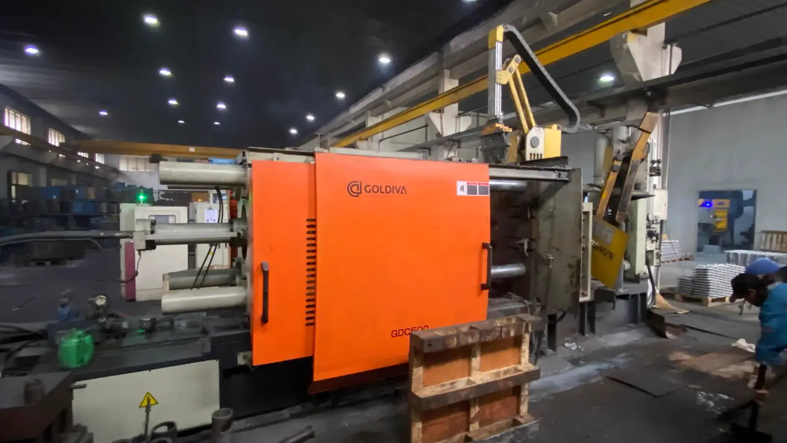
Lead Technical Image
Add a hero-level manufacturing, tooling, or component image that reinforces the article topic above the body copy.
Comparison or Detail Image
Reserve a second image for an alloy comparison, defect example, tooling detail, or application close-up deeper in the article.
Ask an electronics forum how to house a controller that must survive rain, hose-down, or a dunk in shallow water, and the answers converge: a die-cast aluminum enclosure, a designed gasket joint, screws that squeeze it shut. The convergence is earned — a stiff metal box, a controlled seal path, and predictable compression are the standard architecture for waterproof electronics. What the thread rarely spells out is the distance from that answer to a printed IP rating.
This guide covers what an IP rating tests, how the lid joint is designed, where enclosures really leak, and what belongs in the RFQ. One principle runs through it all — design features create the conditions for a rating; the tested assembly confers it.
Why Electronics Designs Keep Landing on Die Cast
An enclosure is the structural frame, the EMI shield, sometimes the heat sink, and always the pressure boundary — and when teams compare metal constructions, the shortlist is nearly always sheet metal, extrusion, and die casting.
Sheet metal wins on cost at low volume and simple geometries. Its sealing weakness is flatness: a fabricated part resists holding a large flange or door flat enough for even gasket compression. Extrusion suits long, prismatic housings, but a closed enclosure needs end plates, and those end-cap joints become the sealing problem the profile could not solve. Die casting takes over when the geometry gets complicated in more than one direction — gasket grooves, screw bosses, connector pockets, ribs, and fins in a single part — so the casting arrives as most of an enclosure, not raw material for one. That architecture underlies aluminum die casting, with the electronics case made in aluminum die casting for electronics.
Two properties do most of the ingress-protection work. Stiffness: a cast, ribbed flange does not bow between screws, so compression stays predictable — sheet metal oil-cans under load, plastic flanges creep over months. Machinability: sealing lands can be machined to the control a gasket needs, which a molded wall cannot offer. Plastic enclosures seal well against different odds (see the FAQ), but among metals, casting puts every feature on one part.
What an IP Rating Tests — and What It Does Not
The IP code rates an enclosure with two digits, the first for solids and the second for water. The enclosure-relevant band reads:
- IP65 — dust-protected; protected against water jets from a nozzle.
- IP66 — dust-tight; protected against powerful water jets: the hose-down class.
- IP67 — dust-tight; protected against temporary immersion, commonly cited as the one-meter, thirty-minute condition of the standard's test.
- IP68 — dust-tight; protected against continuous immersion under conditions the maker declares — depth and duration stated, not implied by the code.
North America's parallel system, NEMA enclosure types, does not convert to IP one-to-one — NEMA 4X is simply the rating most often set beside IP66; the FAQ takes it up directly.
The governing principle: a rating belongs to the complete assembled enclosure, as tested — gasket, lid, screws, glands, connectors, plugs, everything as shipped. An O-ring groove with fasteners outside the seal path is the standard route to an IP6x enclosure, but it becomes a rating only when the whole assembly passes the ingress test. No single feature delivers a rating on its own; features are the route, the test is the destination.
Designing the Seal Path: Grooved O-Ring, Die-Cut Gasket, or Formed Bead
The lid-to-box joint is where enclosure sealing is designed; three constructions are standard, all working by the same physics — an elastomer squeezed to a designed compression fills the gaps that tolerances leave.
O-ring in a groove. The most controlled route. Groove depth and width are calculated so the ring compresses by a designed squeeze — seal manufacturers' guides typically target around 20 to 30 percent of the cross-section for static joints — and so displaced rubber has somewhere to go. The price is tolerance sensitivity: squeeze is the difference between two dimensions, so every error in groove depth, land height, or lid standoff subtracts directly from the seal budget. An offset on the order of a tenth of a millimeter — six thousandths of an inch — can separate a joint that holds from one that weeps. That is why grooves and their lands are normally machined into the casting, with dimensions and position tolerances on the drawing.
Die-cut flat gasket. A stamped silicone, rubber, or foam gasket laid on a flange — more forgiving than an O-ring: it accepts rougher texture and more flatness error across large lids, in exchange for a wider flange, more clamp points, and higher closure force.
Formed-in-place bead. A liquid gasket dispensed and cured in position, conforming to the casting surface as it is. It suits complex seal paths and unmachined faces; the compromises are a joint not meant to be reopened, and bead-height consistency as a supplier process to hold.
One rule on surface condition: as-cast surfaces carry the process's fine texture. For a grooved O-ring the standard practice is a machined sealing land; flat gaskets and formed beads tolerate cast texture more readily. Whichever route, the compression target and its protecting tolerances belong on the drawing.
Fasteners: Outside the Seal Boundary, Spaced for Compression
Two fastener rules carry much of the sealing load.
Placement: outside the sealing boundary. The standard architecture runs lid screws outside the gasket line, threading into cast bosses: no holes pierce the seal path, and compression loads the joint rather than pierces it. Screws through the gasket zone interrupt the seal at every fastener; screws through the sealed wall put a thread-shaped leak path in the boundary. A fastener that must pass through the wall — for a bracket or clamp — needs its own seal, and joins the penetration list below.
Spacing: set by compression, not closure. Between fasteners the lid and flange act as springs: too much span and the joint bows, leaving the gasket under-compressed at mid-span while crushed at the screws. Stiff flanges buy wider spacing; flexible ones demand more screws, each one assembly time and cost. Here the die cast box earns its default status — a cast, ribbed flange is stiff in the net shape, so compression stays predictable, and cast-in bosses put threads where needed. It is why the assembly documentation should carry a torque specification: the gasket performs at its designed compression.
Penetrations: Where Enclosures Actually Leak
A well-designed box joint is rarely the first thing to fail; the openings are. Every connector, pushbutton, lens, gland, and vent is a second sealing problem, miniaturized and stacked onto the first — an IP66 or IP67 enclosure is a system of small sealed openings with a lid.
Two families of answer. Finished IP-rated components — panel connectors, glands, buttons, vents, each with its own ingress rating for its mounted condition — shift that opening's sealing to the component maker; at moderate volumes this is usually cheaper than designing, machining, and validating an equivalent opening in-house, and it deletes an operation from the build. Custom openings — a lens, a feed-through, a machined pocket — are yours: bore tolerance, seal selection, clamp design, validation.
Keep the count honest: one multi-way connector beats six cable glands, seal only what truly needs sealing, and treat blanking plugs as part of the tested configuration — sealed openings too.
From IP66 to IP68: One System Decision at a Time
The route to IP66 is the machinery already described — designed compression joint, screws outside the boundary, machined sealing lands, IP-rated penetrations, tested as an assembly. Beyond that, each step up is a system decision spanning tolerances, machining, gaskets, and test plan — not a matter of more sealant.
IP67 adds immersion. Temporary submersion puts a pressure differential across every seal and the casting wall itself. The standard responses: a tighter compression stack-up (machined groove and land, defined screw torque) and attention to porosity — porosity that machining opens can leak under immersion pressure, and impregnation is an established remedy when it appears.
IP68 adds time and depth. Continuous immersion under maker-declared conditions typically brings the tightest stack-up control, engineered gaskets or formed beads. Potting — filling the enclosure or its electronics with a sealing compound — is one route to IP68, typically reserved for the toughest cases. It is a route, not a prerequisite: designs reach IP68 with a machined flange and a properly compressed gasket alone. And the code always requires a declared condition — "IP68" alone is not a specification.
Coatings cut both ways: they protect against corrosion around the gasket joint, but a finish over a sealing land changes the dimension the gasket sees — sealing lands are commonly masked, and the finish sequence belongs on the drawing. The two common finishes are compared in anodizing versus powder coating.
One Casting, Two Jobs: Gasket Flange and Heat-Sink Fins
Power electronics change the enclosure's job description: the hottest components — MOSFETs, rectifiers, power resistors — end up bolted directly to the enclosure wall, making the housing the heat sink as well as the pressure boundary. Die casting is one of the few constructions carrying both jobs in one part: gasket groove and flange at the joint, fins on the outer wall, a machined pad where the devices mount.
The thermal side is covered in the existing guide to aluminum die casting heat sinks; what matters here is the interaction. Whether an as-cast face can serve as a mounting surface depends on the design's thermal budget — the standard practice is a machined pad with thermal interface material, since flatness at the interface governs contact resistance. And the wall carrying that heat also holds the seal: a heavily heated zone near the flange introduces expansion the compression stack must absorb — an argument for keeping the hottest devices away from the seal land. Alloy choice touches both jobs, compared for the two common enclosure alloys in ADC12 versus A380.
Sizing the Enclosure as the Heat Sink: A Worked Way of Thinking
The question appears at every scale of electronics. At the hobbyist end, a forum builder second-guesses a DC-DC module in a ribbed die-cast aluminum box against the thin sheet-metal enclosure it replaced. At the professional end, an engineer sizes a sealed, fanless controller dissipating on the order of 15 W at 50 °C ambient. The physics is identical, and it is a chain of thermal resistances before it is a parts decision.
The resistance chain. Heat flows junction to component case, across the interface material into the enclosure wall, along the wall, and out of the outer surface by natural convection and radiation together. Two links dominate. The interface: a machined pad with thermal interface material, as above. And the outer surface, whose combined convection-plus-radiation coefficient in still air spans a wide range — roughly 5-15 W/m²·K depending on finish, orientation, and how hot the wall runs. Wall conduction is rarely the limit: die-cast aluminum conducts on the order of 96-110 W/m·K in the common enclosure alloys.
Order-of-magnitude sizing. Take the forum case: 15 W, 50 °C ambient, components rated somewhere in the 85-95 °C region, so the wall may rise roughly 35-45 °C. Required area is Q/(h·ΔT): at h between 6 and 10, the answer lands around 0.04-0.07 m² — a few hundred square centimeters of effective outer surface. The value is the method, not the digits: a thirty-second estimate says whether the plain box passes, or the design needs fins, a lower power budget, or a larger housing — before tooling is cut.
When fins earn their keep. Fins multiply surface only where air moves. Vertical fins in free air work; fins facing downward, or buried inside another cabinet, mostly add weight. Spacing matters as much as height — gaps in the high-single-digit to low-teens millimeter range let buoyant air through, tight comb spacing chokes it — and a painted or anodized surface radiates markedly better than bright bare metal, sometimes worth more than the fins themselves.
The board is part of the path. The standoffs and pillars that hold a PCB steady under vibration, as the sealing sections cover, are also its thermal path: metal standoffs couple board heat into the wall; plastic ones insulate it.
For fin geometry, alloy choice, and the casting specifics, see the aluminum die casting heat sink guide.
What the Die Caster Needs in the RFQ
An enclosure RFQ that ends well hands the die caster four blocks of specifics.
Seal groove geometry and position tolerances. Groove cross-section, sealing land, and position relative to the screw bosses and mating standoff, with datums — the caster can only hold a compression budget the drawing defines.
Machined-face callouts. Which faces are machined — sealing lands, connector pockets, mounting pads — with flatness and surface-finish callouts matched to the seal type; a grooved O-ring land wants tighter control than a flat-gasket flange.
The IP target and test plan. Target rating; the ingress standard the assembly will be tested to (IEC 60529 conditions or the market equivalent); who tests, and at what stage — first article, production sampling. The rating attaches to the complete assembly; the supplier's deliverable is the dimensional control that makes it reachable.
The penetration list. Every connector, gland, button, and plug — part numbers, mounting geometry, and which openings the caster machines versus which arrive as cast pockets or are drilled on your side. A cutout with no part number behind it invites a quote built on guesses.
FAQ
How do IP66 and NEMA 4X relate?
They overlap; they do not convert. Both address dust and hose-directed water. But NEMA types test a wider set of environmental conditions — 4X notably adds corrosion resistance — under different definitions, so an enclosure tested to IP66 does not thereby qualify as NEMA 4X, nor the reverse. If a requirement names both, the enclosure must be evaluated under both.
Can a die cast enclosure reach IP67 without machining?
Not as a rule. The standard route to IP67 includes machined sealing lands, because immersion pressure punishes the tolerance stack that as-cast surfaces carry. Softer flat gaskets tolerate more texture than a grooved O-ring, so some designs seal without machining every face — but whether an enclosure holds is decided by the immersion test on the assembled part, not its construction. When a drawing is silent, a supplier will typically assume machined sealing lands and price accordingly.
Plastic or die cast: which is harder to seal to IP68?
Both reach IP68, against different enemies. Plastic fights time: compression set at assembly relaxes as flanges creep and screw preload fades, so the design needs ribs, generous walls, validation over temperature. Die cast fights the test environment: immersion pressure makes wall and machined-surface porosity a live issue (impregnation is one established remedy), and corrosion under the gasket must be engineered through coatings. Die cast also carries EMI shielding and thermal conduction.
My sealed die cast enclosure traps condensation when it goes from cold to warm — is the seal failing?
How do I mount a panel-mount connector on a drafted (angled) enclosure wall?
Panel-mount connectors — circular connectors, cable glands, D-subs — expect a flat mounting surface, but a die cast wall is drafted so the part ejects from the die. Mounting the connector straight onto the taper seats it against an angled face: uneven compression, a deformed or spinning locknut, and a seal that leaks along the high side. The lowest-cost fix is a spot face: a small flat pad machined into the outer drafted surface at the connector location, so the connector rests against a true perpendicular flat instead of the draft. The machining is seconds of cycle time on a housing whose sealing lands and pocket floors are commonly machined anyway — and it buys a clean seating that no amount of gasket compliance reliably replicates on a taper.
Alternatives when a spot face does not fit the design: specify a local cored boss with a drafted-through hole and machine just its end face (the boss provides wall thickness where the draft thins it), or move the connector to an undrafted machined face and keep the cast walls penetration-free. What does not work is pretending the draft away: a connector torqued onto a drafted wall is a field failure in manufacture. State the spot-face callouts (diameter, depth, surface finish) on the machining drawing along with the other machined features, and the caster prices them like any other machined land.
Send Your Enclosure RFQ to KastMfg
KastMfg is a China-based (Nanjing) die casting manufacturer producing aluminum, zinc, and magnesium high-pressure die castings, with in-house tooling, CNC machining, and DFM review with every quote. Ingress protection is engineered on your drawing — seal geometry, machining callouts, penetration definition — and confirmed by testing the complete assembly. To receive a quotation grounded in your real sealing scope, submit:
- CAD model (STEP/STP) and PDF drawing with revision, including seal groove geometry and machined-face callouts
- Alloy requirement
- Annual volume and expected program life
- Key dimensions and critical-to-seal features: sealing lands, groove-to-boss relationship, flatness
- Surface finish, including coating selection and masking of sealing lands
- Testing requirement, stated as the target IP rating plus the ingress test standard and sampling plan
- Destination country and delivery term
Send your package through the request a quote page or email it to casting@kastdiecast.com.
KastMfg Manufacturing Co., Ltd. Email: casting@kastdiecast.com | Phone: +86 138 1403 4409 No.6, Rungu Road, Nanjing, China
Related
About The Author
Mike Yao on die cast enclosure IP rating
Technical Director, Die Casting Engineering
Technical Director at KastMfg with 20+ years in high-pressure die casting, leading engineering and program management across aluminum, zinc, and magnesium programs for automotive, EV, electronics, and medical OEMs worldwide.
View author profileRelated Reading
Keep exploring the blog
Threaded Holes in Die Cast Aluminum: Guide
Threaded Holes in Die Cast Aluminum: Guide Ask a machining forum whether threads can be tapped straight into die cast aluminum and the answers split into two camps. One calls it...
Mike Yao
12 min read
Die Casting Design Guide: Rules, Tolerances & DFM
Die Casting Design Guide: Rules That Cut Cost and Improve Quality Good die casting design is the single biggest lever on part cost and quality - more than the alloy, more than t...
Mike Yao
5 min read
Can Steel Be Die Cast? Why Conventional HPDC Says No
Can Steel Be Die Cast? Why Conventional HPDC Says No No - steel cannot be made by conventional high-pressure die casting. The commercial process is limited to zinc, magnesium an...
Mike Yao
6 min read
Aluminum Die Casting Electronics Enclosures Guide
Aluminum Die Casting for Electronics Enclosures: EMI Shielding, Tolerances and Finishing Aluminum die casting for electronics enclosures is used when a housing needs mechanical...
Mike Yao
4 min read